Yaskawa YASNAC PC NC Maintenance Manual User Manual
Page 55
PC NC Maintenance Manual
Chapter 4: Troubleshooting
4-34
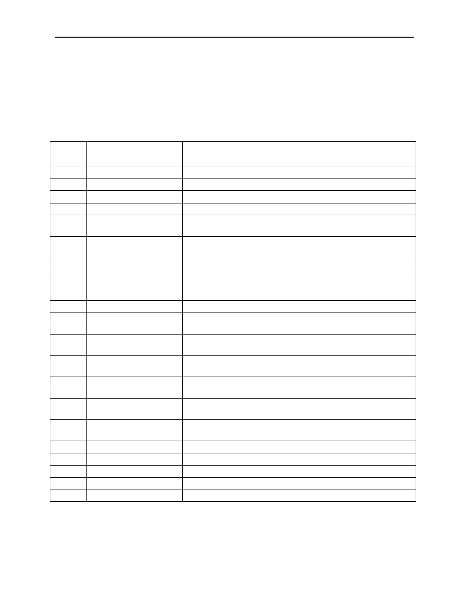
VS-626MR5 Alarm List
In the VS-626MR5, the protective functions operate according to the error
content when a fault and an error phenomenon are generated during a drive
operation when the drive is stopped. This error content is displayed on the
7 segment LED, according to alarm number.
Table 4.17: Alarm List
Alarm
Number
Name Content
01
Overcurrent
Output current flowed more than the overcurrent detection level.
04
Main circuit fuse is blown
Main circuit fuse is blown.
05
Overload
Output current exceeded the overload level.
11
Output overvoltage
Output voltage exceeded the overvoltage setting value.
12
Main circuit low voltage
Main circuit input voltage went below the low voltage detection level
while driving.
13
Control circuit low voltage Control circuit power supply went below the low voltage detection
level.
14
Power failure for servo
driver
Control voltage supplied to the servo driver is abnormal.
15
Power supply frequency
error
Power supply frequency excessive deviation (50Hz or 60Hz±6%)
16
An initial charge defect
Main circuit condenser charge was not completed in the setting time.
23
Built-in MC defective per-
formance
Magnetic contactor does not work.
43
Heat sink over heating 1
(minor fault)
Heat sink temperature exceeded the upper limit.
44
Heat sink overheating 2
Heat sink temperature exceeded the upper limit and has passed one
minute or more.
45
Heat sink thermistor dis-
connection
Thermistor for the heat sink temperature detection was discon-
nected.
46 Control
card
temperature
error (minor fault)
Control card temperature exceeded +80ºC.
47 Control
card
temperature
error 2
Control card temperature exceeded +85ºC.
d2
CPU built-in A/D defective
Built-in A/D converter is defective.
F0
ROM defect
Memory (PROM) is defective.
F1
EEPROM defect
Memory (EEPROM) is defective.
F5
CPU defect
Internal RAM check error (at initialization).
• •
Control card fault
WDT time-out