Yaskawa YASNAC PC NC Maintenance Manual User Manual
Page 171
PC NC Maintenance Manual
The VS-626M5
4-150
Notes on resetting faults
•
To reset a fault by the digital operator after removing the cause,
depress the RESET key in fault display mode. In other modes, the
RESET key cannot reset the fault.
•
Before resetting, turn OFF run command signals (FWD, REV, ORT)
that are input externally.
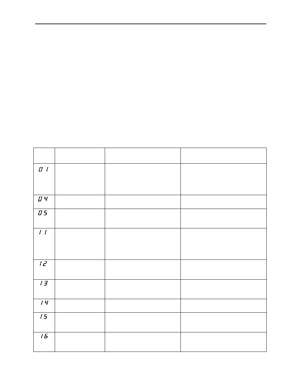
List Of Converter Faults
If a fault occurs during operation, protective functions are activated
(depending on the fault) and operation is stopped. The contents of the
faults are displayed on the 7-segment LED in numbers.
Table 4.36: Fault Diagnosis and Corrective Actions of Converter
Fault
No. 22
Name
Contents
Corrective Actions
Overcurrent
Output current exceeded over-
current detection level.
Check the wiring.
Check the input supply voltage.
Check the AC reactor.
Check the load shaft (inverter, servo)
capacity.
Main circuit fuse
blown
Main circuit fuse was blown.
Check for damaged transistor, load
side short circuit, grounding, etc.
Overload
Output current exceeded over-
load level.
Reduce the load.
Check the load shaft (inverter, servo)
capacity.
Output overvoltage
Output voltage exceeded over-
voltage level.
Detection level:
200V class: Approx. 400V
400V class: Approx. 800V
Check the input supply voltage.
Check the load shaft (inverter, servo)
capacity.
Main circuit under-
voltage
Main circuit input voltage became
lower than undervoltage detec-
tion level.
Check the input supply voltage.
Control circuit under-
voltage
Control circuit power supply
became lower than undervoltage
detection level.
Check the control supply voltage.
Servo unit power
supply fault
Control supply voltage supplied
to servo unit was not normal.
—
Power supply
frequency fault
Excessive power supply fre-
quency deviation (50Hz or 60Hz
±5%)
Check the input power waveform.
Initial charging fault
Charging of main circuit capacitor
was not completed within set
time.
Replace the unit.