Yaskawa YASNAC PC NC Maintenance Manual User Manual
Page 177
PC NC Maintenance Manual
The VS-626M5
4-156
Motor Faults And Corrective Actions
If any of the following faults occurs in the motor, check the cause and pro-
vide the relevant corrective actions.
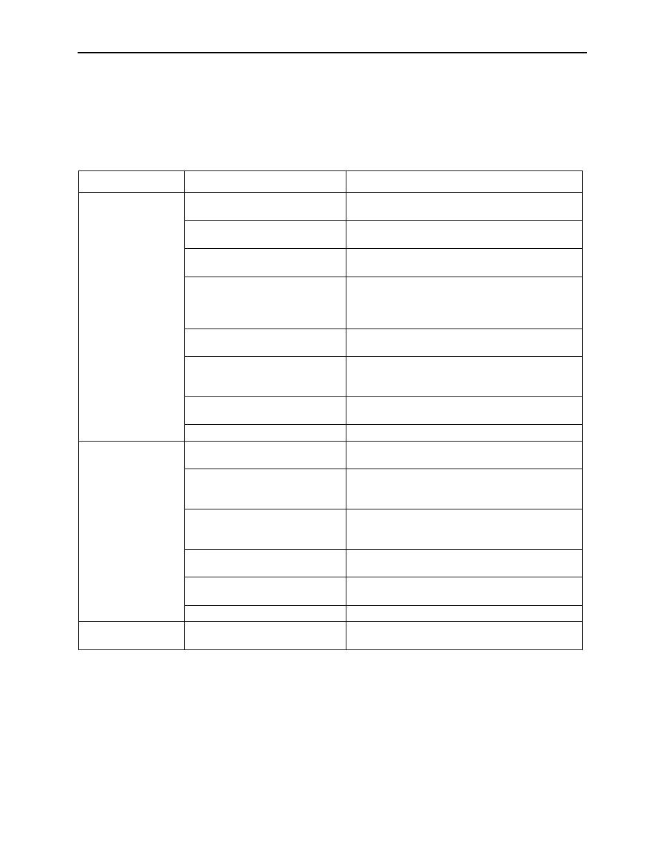
Table 4.38: Motor Faults and Corrective Actions
Fault
Cause
Corrective Action
Motor does not rotate.
Protective function has been acti-
vated.
Check fault number. and carry out appropriate steps.
Converter main circuit power is not
turn ON.
Turn ON power supply.
Check supply voltage.
Inverter output disconnection,
improper connection
Check the wiring between inverter and motor.
Control signal does not function.
Check sequence input signal on operation status dis-
play (U1-09) (RDY, EMG, FWD and REV).
Check if speed reference is input or not on operation
status display (U1-02).
Torque limiting
Check whether external torque limit signals TLL or
TLH is input on operation status display (U1-09).
Motor winding wire disconnection
Check resistance between motor terminals (a circuit
tester necessary).
Replace the motor.
Motor fault (rotor and stator rub
together, broken bearing)
Check motor shaft rotation manually.
Replace the motor.
Control PC board fault
Replace the control PC board.
Motor rotates slowly or
vibrates with no rota-
tion.
Inverter output disconnection,
improper connection
Check the wiring between inverter and motor.
Encoder signal line disconnection,
improper connection, loose connec-
tor
Check the wiring of encoder signal line.
Motor encoder fault
Check for abnormal changes in motor speed on
speedometer or operation status display (U1-01).
Replace the encoder or the motor.
Speed reference signal disconnec-
tion, improper connection
Check the wiring of speed reference signal.
Torque limiting
Check whether external torque limit signals TLL or
TLH is input on operation status display (U1-09).
Control PC board fault
Replace the control PC board.
Motor rotates in
reverse direction.
Improper connection of inverter out-
put or motor encoder signal line
Check the wiring according to the connection dia-
gram.