Table 4.28: control circuit signals (6cn) – Yaskawa YASNAC PC NC Maintenance Manual User Manual
Page 139
PC NC Maintenance Manual
The VS-626M5
4-118
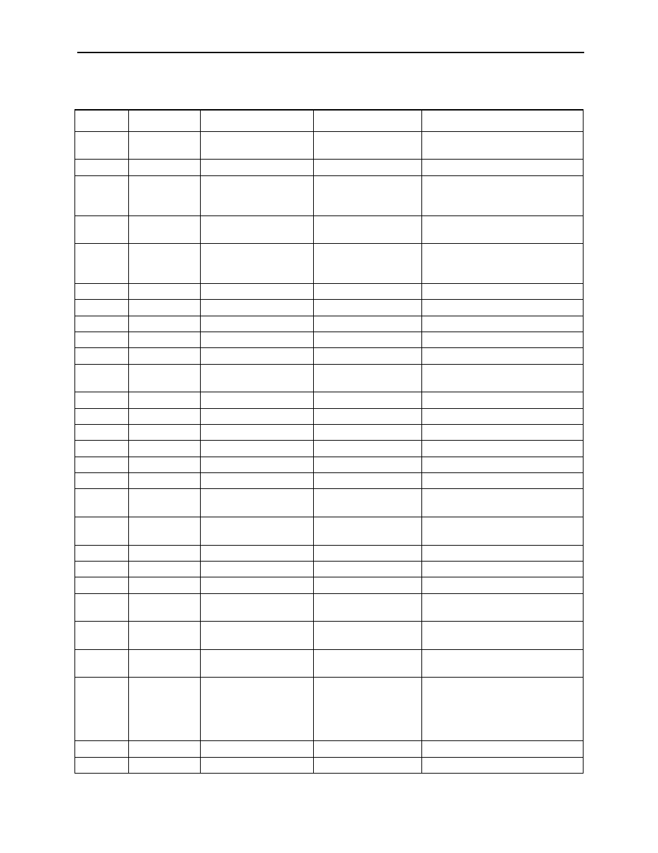
Table 4.28: Control Circuit Signals (6CN)
Signal
Number
Function
Signal Level
Related Constants
+15V
1
+15V output
+15V Load current:
10mA or less
C1-26, 10, C1-38 bit 5
C1-11, 12
SS
2
Shield (0V)
_|
SCOM
3
Analog speed reference
input
0 to _}10V
(Input impedance:
50kĦ)
0V
4
Analog speed reference
0V
_|
DAS
5
Digital/analog speed ref-
erence selection
24VDC
Current when closed:
5mA
C1-36 bit 7
RDY
6
Operation ready
Selected when C1-37 bit 2=0
EMG2
Emergency stop 2
Selected when C1-37 bit 2=1
EMG
7
Emergency stop
_|
FWD
8
Forward run
_|
REV
9
Reverse run
_|
TLH
10
Torque limit H
Selected when C1-36 bit 2=0
C1-26, C1-38 bit 2
TLL
11
Torque limit L
Selected when C1-36 bit 1, 0=00
INC
Incremental
Selected when C1-36 bit 1, 0=10
SSC
12
Soft start cancel
Selected when C1-36 bit 3=0
SV
Servo mode
Selected when C1-36 bit 3=1
RST
13
Fault reset
_|
CHW
14
Winding selection
_|
PPI
15
P control/PI control
selection
Selected when C1-36 bit 4=0
ORT
16
Orientation
Selected when C1-40 bit 3=0
C1-39 bit 0
NCORT
NC orientation
Selected when C1-40 bit 3=1
LGR
17
L gear selection
C1-27, 28, 29
MGR
18
M gear selection
EXTCOM0 19 to 21
Sequence input signal
power supply common
_|
24VCOM
22, 23
Sequence input signal
power supply 24V
_|
0VCOM
24, 25
Sequence input signal
power supply 0V
_|
FC0
26
Fault code 0
Open-collector output
Exclusive-use for
24VDC
Load current: 50mA or
less
_|
FC1
27
Fault code 1
FC2
28
Fault code 2