Table 4.26: control signal connectors (continued) – Yaskawa YASNAC PC NC Maintenance Manual User Manual
Page 136
The VS-626M5
PC NC Maintenance Manual
4-115
Note:
Some of the connectors attached with control PC board and option cards are of the same type.
Therefore, care must be used to mount the cards to the correct connectors, each of which is identi-
fied by a device symbol. If an incorrect connection is made, damage to the inverter may occur.
9CN
Load shaft
encoder signal
output
10214–
52A2JL
·10114–
3000VE
·10314–
52A0–008
(case)
0.2 mm
2
Sumitomo 3M
Ltd.
Magnetic
Sensor
Method
Orientation
Card
(VS-626M5)
10CN
Control signals 10214–
52A2JL
·10114–
3000VE
·10314–
52A0–008
(case)
0.2 mm
2
Sumitomo 3M
Ltd.
Control PC
Board
(VS-
656MR5)
5CN
Control signal
connector with
other drive unit
8831E–034–
170LD
8822E–
034–171D
Use a special
cable.
KEL Corp.
1CN
Communica-
tion cable
connector (for
factory test
prior to ship-
ment)
10214–
52A2JL
·10114–
3000VE
·10314–
52A0–008
(case)
„Ÿ
Sumitomo 3M
Ltd.
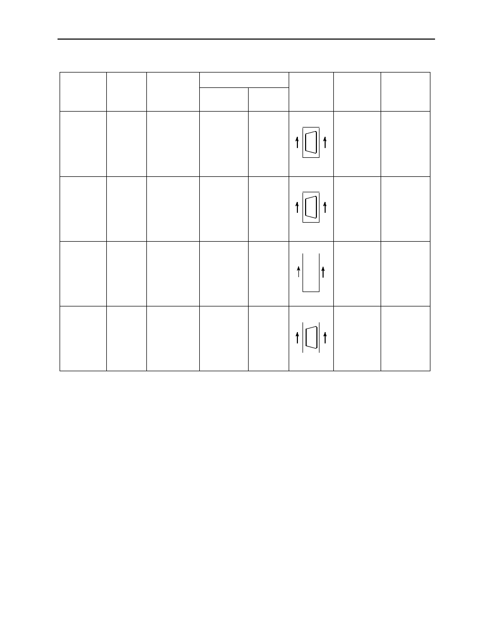
Table 4.26: Control Signal Connectors (Continued)
Connector
Number
Function
Connector Type
Connector
Pin
Numbers
Applicable
Maximum
Wire Size
Connector
Manufacturer
Inverter Side
Wiring
Side
14
8
7
1
14
8
7
1
34
32
4
2
33
31
3
1
14
8
7
1