Yaskawa YASNAC PC NC Maintenance Manual User Manual
Page 175
PC NC Maintenance Manual
The VS-626M5
4-154
Phase C signal
detection error
Phase C signal could not be
detected during tuning up.
Check the wiring of encoder sig-
nal lines.
Check that encoder signal lines
are separated from main circuit
or other power lines.
Verify that motor and inverter
are grounded.
Replace the orientation card.
Replace the encoder.
_œ_›_›_œ
Phase C signal
width error
Phase C signal width
exceeded 100 pulses.
_œ_›_›_œ
Fault of number of
pulses per rotation
(Encoder method
orientation)
Number of pulses per rotation
exceeded 4096 _} 1 during
tuning up.
_œ_›_›_œ
Position detection
signal cable
disconnection
Position detection encoder
signal cable was disconnected
or connected improperly.
Check the wiring of load shaft
encoder signal lines.
Replace the load shaft encoder.
Replace the orientation card.
_œ_›_›_œ
INC signal error
(Encoder method
orientation)
INC signal input timing error
(minor fault)
After carrying out absolute posi-
tioning, change circuit to com-
mand INC signal.
_œ_›_›_œ
Tune-up
incomplete
(magnetic sensor
method orienta-
tion)
Orientation command was
input before tuning up (minor
fault).
Perform orientation tune-up.
_œ_›_›_›
Magnetic sensor
signal detection
error
Incorrect magnetic sensor sig-
nal voltage level during tuning
up.
Check the wiring of magnetic
sensor signal lines.
Replace the magnetic sensor or
magnetizer.
_œ_›_›_›
Fault of number of
pulses per rotation
(magnetic sensor
method orienta-
tion)
Number of motor pulses per
spindle rotation (4096 __
speed gear ratio) exceeded
_}6% during tuning up.
Check control constants C1-27,
28, 29.
Check the wiring of motor
encoder signal lines.
_œ_›_›_›
Magnetic sensor
signal disconnec-
tion
Magnetic sensor signal cable
was disconnected or con-
nected improperly.
Check the wiring of magnetic
sensor signal lines.
Replace the magnetic sensor or
magnetizer.
Perform tune-up again.
_œ_›_›_›
INC signal error
(Magnetic sensor
method orienta-
tion)
INC signal input timing error
(minor fault)
After carrying out absolute posi-
tioning, change circuit to com-
mand INC signal.
_œ_›_›_›
Speed reference
A/D converter
error
I/O card speed reference A/D
converter error
Replace the I/O card.
_›_›_œ_›
CPU built-in A/D
converter error
CPU built-in A/D converter
error
Replace the control PC board.
_›_›_œ_›
Phase U A/D
converter error
Phase U current detection A/D
converter error
_›_›_œ_›
Phase W A/D
converter error
Phase W current detection A/
D converter error
Replace the control PC board.
_›_›_œ_›
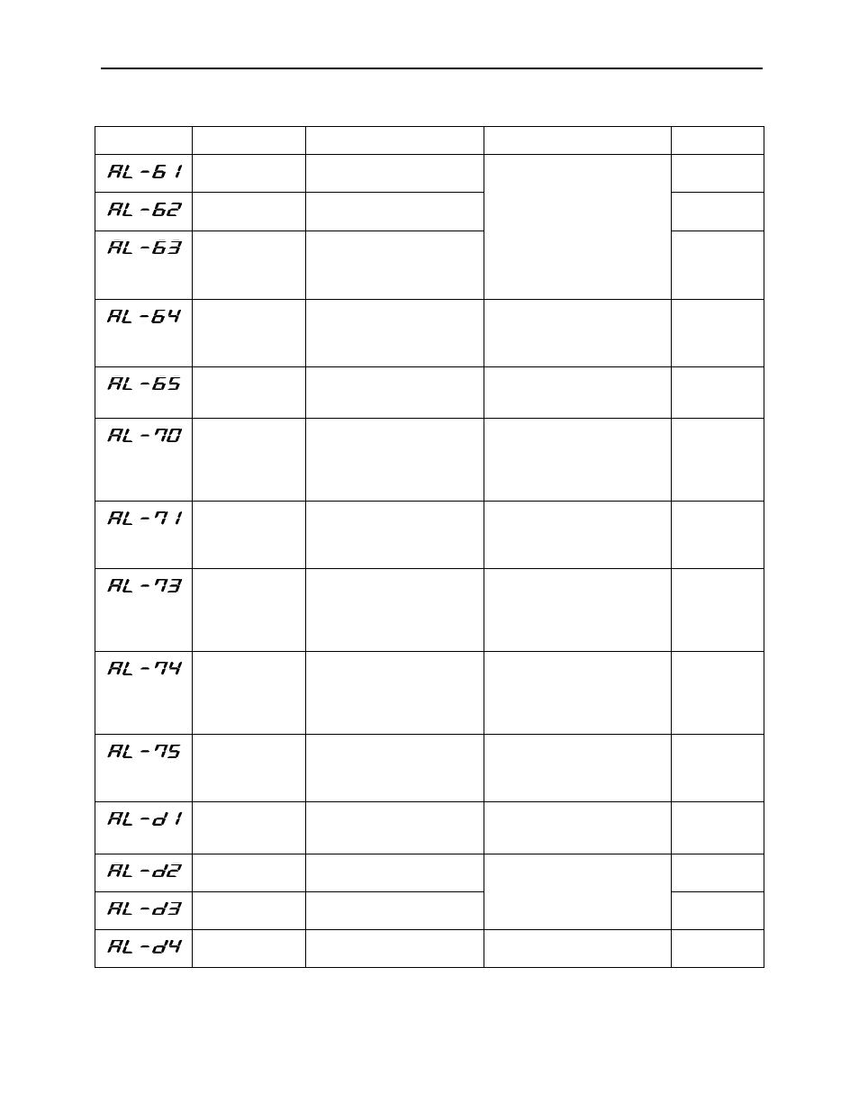
Table 4.37: Fault Diagnosis and Inverter Corrective Actions (Continued)
Fault Number
Name
Contents
Corrective Action
Fault Code