Yaskawa YASNAC PC NC Maintenance Manual User Manual
Page 137
PC NC Maintenance Manual
The VS-626M5
4-116
Wiring The Control Circuit
The following tables outline the functions of the control circuit signals.
1. Control Signals
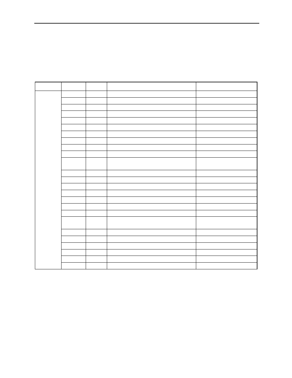
Table 4.27: Control Circuit Signals (1, 2CN)
Connector
Signal
Number
Function
Signal Level
1CN
+24VIN
1
_|
_|
/EXT1
2
_|
_|
/EXT2
3
_|
_|
ESP0
4
_|
_|
ESP1
5
_|
_|
ALM+
6
_|
_|
ALM-
7
_|
_|
ALMC
8
_|
_|
BAT-
9
_|
_|
BAT+
10
_|
_|
PAO
13
Encoder phase A signal output
RS-422A specification
Line driver
*PAO
14
PBO
15
Encoder phase B signal output
*PBO
16
PCO
11
Encoder phase C signal output
*PCO
12
SS
17
Shield (0V)
_|
0V
18
0V
_|
D1 to D12 19 to 30 12–bit digital references 1 to 12
24VDC (Current when
closed: 5mA)
EXTCOM 31
12–bit digital signal common
24VCOM
32
12–bit digital signal power supply +24V
0VCOM
33
12–bit digital signal power supply 0V
VCC
34
_|
_|
MNTR1
35
_|
_|
MNTR2
36
_|
_|