Yaskawa YASNAC PC NC Maintenance Manual User Manual
Page 173
PC NC Maintenance Manual
The VS-626M5
4-152
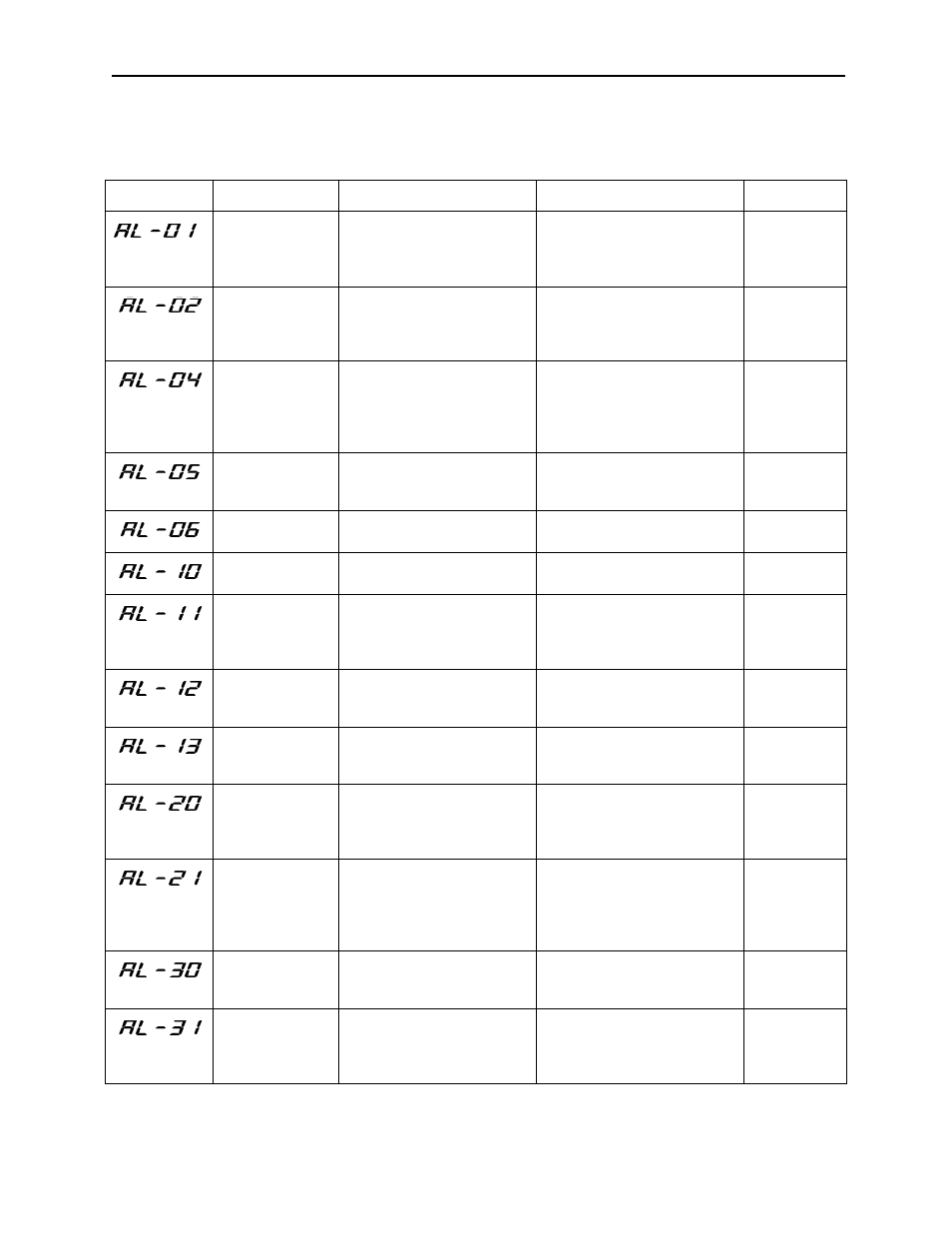
Table 4.37: Fault Diagnosis and Inverter Corrective Actions
Fault Number
Name
Contents
Corrective Action
Fault Code
Overcurrent
Output current exceeded
overcurrent detection value, or
inverter output (load) was
short-circuited.
Check for loose wires.
_œ_œ_œ_œ
Ground fault
Inverter output side ground
current exceeded grounding
detection level.
Check the motor for deteriora-
tion of insulation.
Check the wiring between
inverter and motor.
_œ_œ_œ_œ
Main circuit fuse
blown
DC circuit fuse was blown.
Check for damage to transistor,
short-circuits on load side,
ground fault, etc.
Check the inverter output wir-
ing.
_œ_œ_œ_œ
Inverter output
overload
Output current of 120% of 30-
minute rating runs for over
one minute.
Reduce the load.
Check the load shaft (inverter,
servo) capacity.
_œ_œ_œ_œ
Motor overload
Motor overload capacity
exceeded.
Reduce the load.
_œ_œ_œ_œ
Converter fault
A fault occurred in the con-
verter unit.
Check fault contents by using
converter LED.
_œ_œ_œ_›
Main circuit over-
voltage
Main circuit DC bus voltage
exceeded the overvoltage set
value.
Check the input supply voltage.
Check the load shaft (inverter,
servo) capacity.
Check the control constants.
_œ_œ_œ_›
Main circuit under-
voltage
Main circuit DC bus voltage
became lower than undervolt-
age detection level during run.
Check the input supply voltage.
_œ_œ_œ_›
Control circuit und-
ervoltage
Control circuit power supply
became lower than undervolt-
age detection level.
Check the control supply volt-
age.
_œ_œ_œ_›
Winding selection
fault
Winding selection was not
completed within set time.
Check the control constant C1-
25.
Check magnetic contactor wir-
ing for winding selection.
_œ_œ_›_œ
Emergency stop
fault
Inverter did not stop within 10
seconds after emergency stop
command.
Check control constant C1-25.
Check the setting of control con-
stant C1-24 and whether exter-
nal torque limit signals TLL and
TLH are input.
_œ_œ_›_œ
Encoder signal
cable disconnec-
tion
Motor encoder signal was dis-
connected or connected
improperly.
Check the wiring of encoder sig-
nal lines.
_œ_œ_›_›
Motor overspeed
Motor speed exceeded 120%
of set rated speed.
Check that encoder signal lines
are separated from main circuit
or other power lines.
Check the control constants.
_œ_œ_›_›