Yaskawa YASNAC PC NC Maintenance Manual User Manual
Page 184
PC NC Maintenance Manual
Chapter 6: Module/Unit Replacement
6-2
4.
Insert all connectors and cables in their original locations.
5.
Return the power supply switch for the CPU rack to the “I” posi-
tion and power up to restart the control unit.
6.
Change the NC controller serial number.
7.
Follow the NC board data set-up procedures.
Following NC board installation, verify functions as follows.
1.
Ensure that the +5V and +24V status lamps on the NC card are lit.
2.
Verify that the NC card operates normally by looking at the mov-
ing pattern of status lights 1, 2, 3, 4.
3.
Verify that the NC operates normally after the SERVO ON switch
is pressed and that no alarms show on the MMI screen.
4.
Verify that the NC starts the shutdown sequence after the SHUT
DOWN switch is pressed.
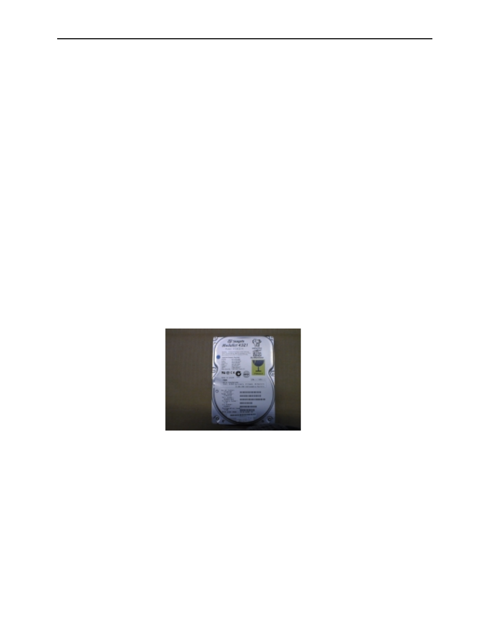
Hard Disk Drive Unit
Removal of the hard disk drive unit is performed as follows.
1.
Turn the main power off; set the power supply switch for the rack
to the “O” position.
2.
Remove the rack door by first loosening the top/bottom thumb-
screws and removing the data (HD DATA) and power (HD PWR)
cables from the hard disk drive. Push the door upward to disen-
gage side-pins from the door hinges.
3.
Place the door assembly on a flat, steady surface and remove the