Yaskawa YASNAC PC NC Maintenance Manual User Manual
Page 147
PC NC Maintenance Manual
The VS-626M5
4-126
Figure 4.16: Input Method Selection
4. Precautions on Wiring Power Lines and Control Signal Lines
For proper wiring between devices, pay attention to the following points in
the design stage.
•
Design the wiring route of the control signal lines (1, 2, 6CN) in
such a way that they are separated from the main circuit wiring
(R/L1, S/L2, T/L3) or other power lines.
If the power lines are provided with the signal lines (motor
encoder signal lines), a malfunction may be caused by the effect
of noise generated from the power lines.
•
The length of the control signal lines (including the motor
encoder signal lines) must be less than 20m.
Excessively long motor encoder signal lines reduce the encoder
power supply voltage due to a voltage drop in the signal lines
which may cause the inverter to malfunction.
•
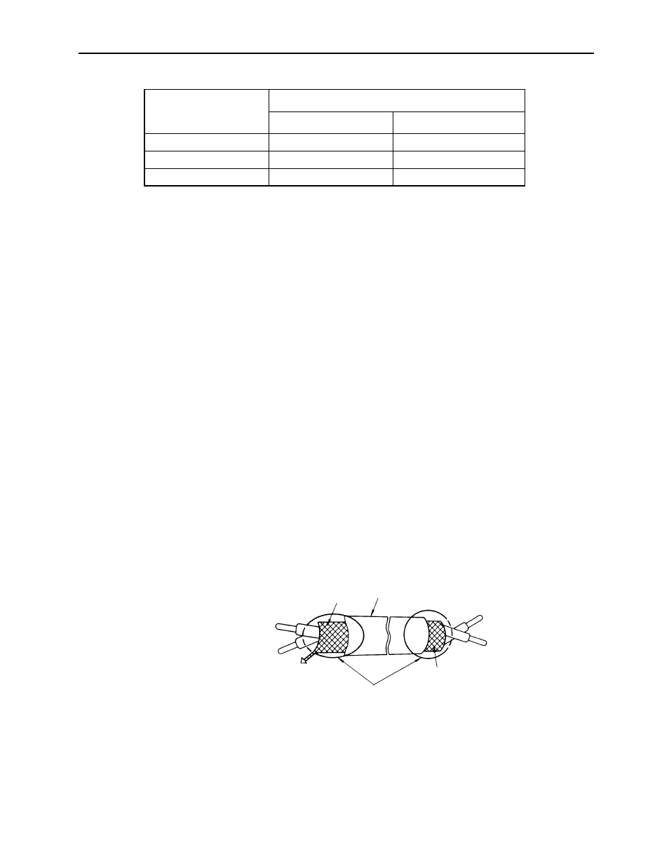
When twisted shielded wires are used for control signal lines, ter-
minate them as shown in the figure below.
Figure 4.17: Shielded Wire Termination
Signal Name
Pin Number
1CN
6CN
EXTCOM
31
19, 20, 21
24VCOM
32
22, 23
0VCOM
33
24, 25
Shielded Sheath
Armor
To inverter shielded
sheath terminal
Insulate these parts
with insulating tape.
Never connect.