Yaskawa YASNAC PC NC Maintenance Manual User Manual
Page 150
The VS-626M5
PC NC Maintenance Manual
4-129
1. Turning ON the Control Power Supply
When the control power supply is turned ON, “
” is displayed in the
converter 7-segment LED display section and “
” is displayed in the
inverter 7-segment LED display section. If they do not appear, search for
the cause, referring to the list of fault displays.
2. Turning ON the Main Circuit Power Supply
When the main circuit power supply is turned ON, the converter 7-segment
LED display is changed to “
.” At the same time, the inverter and the
converter CHARGE LEDs are lit in red. If any fault is displayed, search
for the cause, referring to the list of fault displays.
When “
” is displayed continuously on the 7-segment LED of the con-
verter, the main circuit input voltage may be low or an open-phase may be
occurring. Check the input supply voltage.
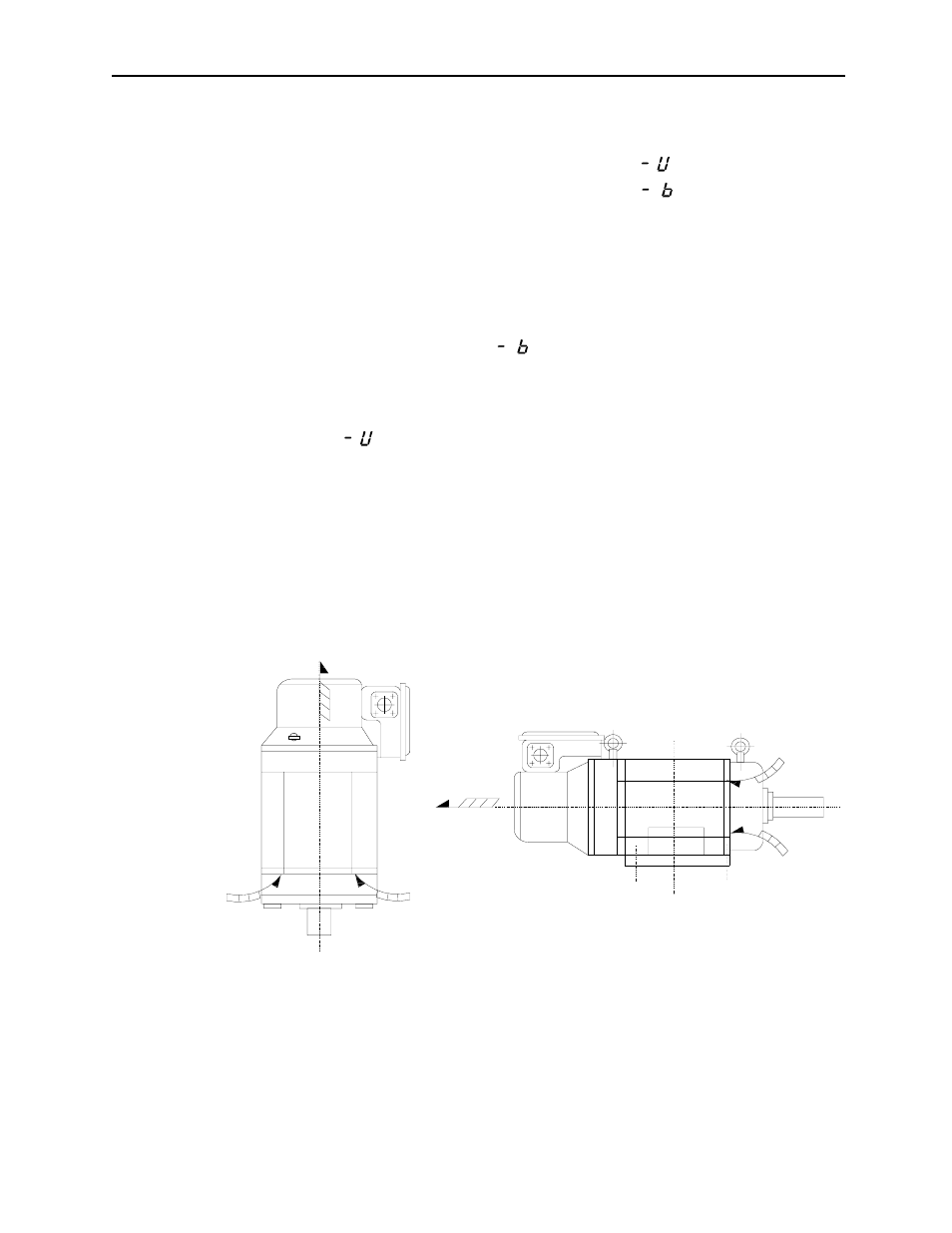
3. Checking the Motor Cooling Fan
When the main circuit power supply is turned ON, the motor cooling fan
begins to rotate. Verify that the cooling air for the motor flows in the cor-
rect direction.
According to the standard specifications, the cooling air
enters from the drive end and leaves from opposite the drive end.
Figure 4.19: Motor Cooling Air Passage
(a) @Flange-mounted Type
(b)
@Foot-mounted Type
Flange mounted type
Foot mounted type