Lith ium – Yaskawa YASNAC PC NC Maintenance Manual User Manual
Page 7
PC NC Maintenance Manual
Chapter 1: General Installation and Electrical Connection
1-4
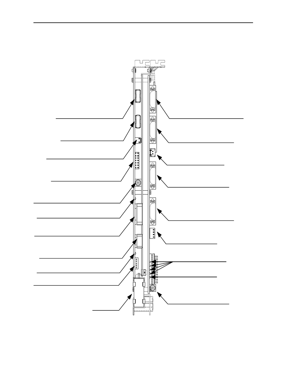
Connector Layout NC Side
The following figure provides a detailed Connectors Layout of the YAS-
NAC JZNC-JFC10 board.
Figure 1.4: Detailed Layout of the YASNAC JZNC-JFC10 Board
LITH
IUM
I/O module power output verification LED
I/O module power input verification LED
Servo controller connector (CN01)
I/O module connector (CN02)
Power good signal connector (CN03)
Interruption setting short pin (S11)
Memory address setting rotary switch (S12)
I/O module power output connector (CN04)
I/O module power input connector (CN05)
attery power reply supply connector (CN06)
Battery
Servo controller I/O connector (CN11)
Power On/Off connector (CN12)
Fuse (HM03, 0.3A) (F1)
RS232C connector (CN14)
Direct IN/OUT connector (CN14)
System load switch (S1)
System load rotary switch (S1)
Battery alarm LED
System load switch (S1)
(from top: 1, 2, 3, 4)