Yaskawa YASNAC PC NC Maintenance Manual User Manual
Page 26
Chapter 4: Troubleshooting
PC NC Maintenance Manual
4-5
(2)
Alarm Numbers 2061 to 2068 (Reference Point Return Area
Error)
(3)
Alarm Numbers 2071 to 2078, 2081 to 2088 (Reference Point
Return Position Error)
Table 4.3: Troubleshooting - Alarm #2061 ~ 2068 (Reference Point Return Area Error)
Cause Check
Item
Countermeasures
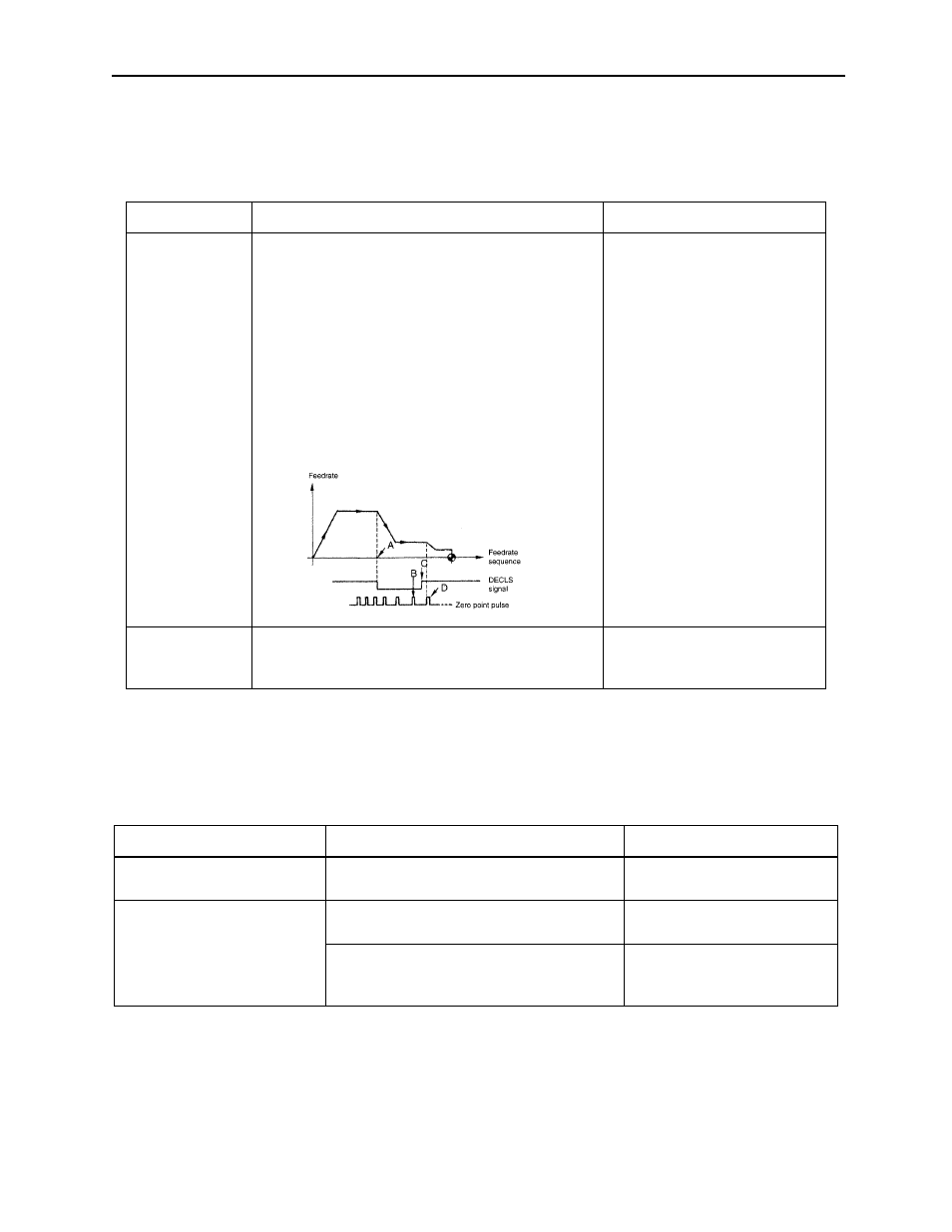
The reference
point return start
point is at the
zero point side
of the decelera-
tion limit switch.
Deceleration limit switch (DECLS)
If reference point return is started from a point
located at the reference point side of DECL (point
C) as shown below, an alarm occurs.
Note:
This error check is not made before the
execution of manual reference point
return after the power is turned ON.
Return the axis to a position on
the deceleration LS or away
from it and, then execute refer-
ence point return once again.
Approach
feedrate is too
fast.
Compare the setting for the approach feedrate
parameter with the parameter list.
Change the setting for param-
eters pm2521 to pm2525 to an
appropriate value.
Table 4.4: Troubleshooting - Alarm Numbers 2071 ~ 2078, 2081 ~ 2088
(Reference Point Return Position Error)
Cause Check
Item
Countermeasures
Alarm in manual reference
point return operation
Determine whether the error occurs every
time.
Contact a Yaskawa customer
service representative.
Alarm in automatic reference
point return operation
G28:
Determine whether the alarm
occurs every time.
Contact a Yaskawa customer
service representative.
G27:
Check the point specified in the
program to determine whether it
agrees with the zero point.
Review the program.
#3073 DO (1st axis)
#3073 D1 (2nd. axis)
#3073 D2 (3rd axis)
#3073 D3 (4th axis)
#3073 D4 (5th axis)
Execute reference
point return again
while observing the
I/O signal monitor
screen