7 speed loop compensation – Yaskawa Sigma Mini User Manual
Page 102
APPLICATIONS
2.6.7 Speed Loop Compensation
— 2-58 —
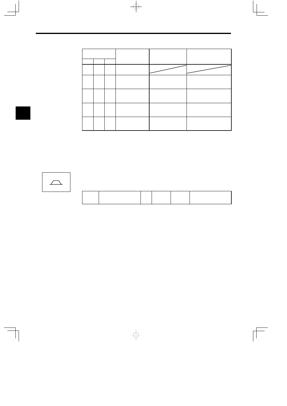
Memory Switch
Cn-01
Mode Switch Set-
ting
Parameter
Unit
Bit D
Bit C
Bit B
ting
Parameter
Unit
-
-
1
Does not use
mode switch.
0
0
0
Uses torque refer-
ence as a detec-
tion point.
Cn-0C
Percentage of rated
torque: %
0
1
0
Uses speed refer-
ence as a detec-
tion point.
Cn-0D
Motor speed: min
−1
1
0
0
Uses acceleration
reference as a
detection point.
Cn-0E
Acceleration reference in-
side the Servopack:
10 (min
−1
)/s
1
1
0
Uses error pulse
as a detection
point.
Cn-0F
Reference unit
Parameter Cn-0F is for position control only.
2.6.7 Speed Loop Compensation
1) This function compensates for the phase-delay generated by the digital control speed
detection. For this function, use the following constant.
Cn-28
NDBCC
Speed Loop
Compensation Constant
Unit:
Setting
Range: 0
to 100
Factory
Setting: 0
For Speed/Torque
Control
First, adjust the servo (position/speed loop gain, speed loop, integration time constant,
torque reference filter) appropriately in the “Cn-28 = 0” status.
Next, gradually increase the set value of Cn-28 from 0, find the proper value at which
noise and oscillation are minimal.
Note Use the speed loop compensation function (set value of Cn-28 is other than 0)
under the following conditions:
⋅ No servo system oscillation
⋅ No abnormal noise from the machine
Even if the speed loop compensation function is used, it may bring little effect or
even increase the oscillation. In these cases, stop using the speed loop com-
pensation function. (Set the value of Cn-28 to 0, again.)
2
Speed/Torque