5 electronic gear – Yaskawa Sigma Mini User Manual
Page 68
APPLICATIONS
2.2.5 Electronic Gear
— 2-24 —
2.2.5 Electronic Gear
The electronic gear function enables the motor travel distance per input reference pulse to be
set to any value. It allows the host controller to perform control without having to consider the
machine gear ratio and the number of encoder pulses.
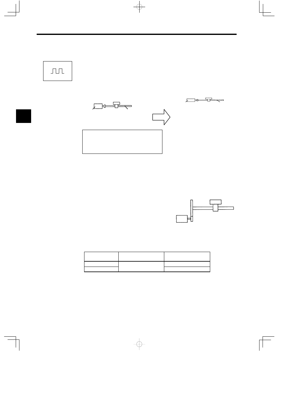
When Electronic Gear Function
is Not Used
When Electronic Gear Func-
tion is Used
Workpiece
Number of
encoder
pulses: 2048
Ball screw
pitch: 6 mm
Reference
unit: 1 μm
To move a workpiece 10 mm,
One revolution is equivalent to 6 mm, so
10 6 = 1.6666 (revolutions)
2048 x 4 (pulses) is equivalent to one revolution, so
1.6666 x 2048 x 4 = 13653 (pulses)
A total of 13653 pulses must be input as a reference.
the host controller needs to make this calculation.
Machine conditions and reference unit
must be defined for the electronic gear
function beforehand.
To move a workpiece 10 mm:
Reference unit is 1 μm, so
10 mm 1 μm = 10,000 pulses
Number of
encoder
pulses: 2048
Ball screw
pitch: 6 mm
Workpiece
Setting the Electronic Gear
Calculate the electronic gear ratio (B/A) according to the procedure below and set the value in
Cn-24 and Cn-25.
1) Check the machine specifications.
Items related to electronic gear:
− Gear ratio
− Ball screw pitch
− Pulley diameter
2) Check the number of encoder pulses for the Servomotor.
Motor Model
Encoder Type
Number of Encoder
Pulses Per Revolution
SGMM-AjC31j
Incremental encoder
2048
SGMM-BjCF1j
1024
Same as parameter Cn-11 settings.
2
Positions
Gear ratio
Ball screw pitch