2 mechanical characteristics – Yaskawa Sigma Mini User Manual
Page 166

SERVO SELECTION AND DATA SHEETS
4.2.2 Mechanical Characteristics
— 4-16 —
4.2.2 Mechanical Characteristics
The mechanical characteristics of the Servomotor are described here.
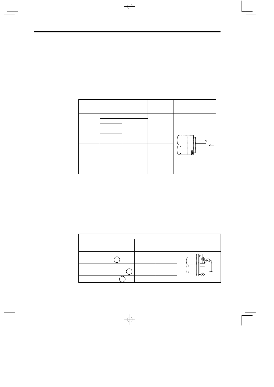
Allowable Radial Load, Allowable Thrust Load
The output shaft allowable loads for Servomotors are shown below.
Conduct mechanical design so that the thrust loads and radial loads do not exceed the
following values.
Servomotor Model
SGMM-
Allowable
Radial Load
Fr [N(lb)]
Allowable
Thrust Load
Fs [N(lb)]
Reference Drawing
Standard
A1C31jj
34.1 (7.7)
14.7 (3.3)
A2C31jj
44.1 (9.9)
(
)
A3C31jj
(
)
B3CF1j
8 (1.8)
4.0 (0.9)
F
B5CF1j
(
)
(
)
Fr
B9CF1j
10 (2.2)
Fs
With Gears
A1C3JAjj
51.9 (11.7)
47.0 (10.5)
Fs
A2C3JAjj
(
)
(
)
A1C3JBjj
76.4 (17.2)
A2C3JBjj
(
)
A1C3JCjj
89.2 (20.1)
A2C3JCjj
(
)
Note a) The box (j) at the end of the model number is for the shaft specifications.
b) The allowable load is applied to the shaft end.
Mechanical Tolerance
The tolerances of the Servomotor output shaft and installation are shown in the following
table.
Tolerance (T.I.R.)
Reference Diagram
Standard
With Re-
duction
Gears
g
Perpendicularity between flange
face and output shaft
A
0.04
0.06
Mating concentricity of flange O.D.
B
0.04
0.05
Run-out at end of shaft
C
0.02
0.04
Note T.I.R. = Total Indicator Reading