9 wiring examples, Emc directive measures – Yaskawa Sigma Mini User Manual
Page 246
EMC DIRECTIVE MEASURES
6.2.9 Wiring Examples
— 6-8 —
Cable Line
Encoder Line
Motor Line
Line Position
Servopack end
Motor end
Servopack end
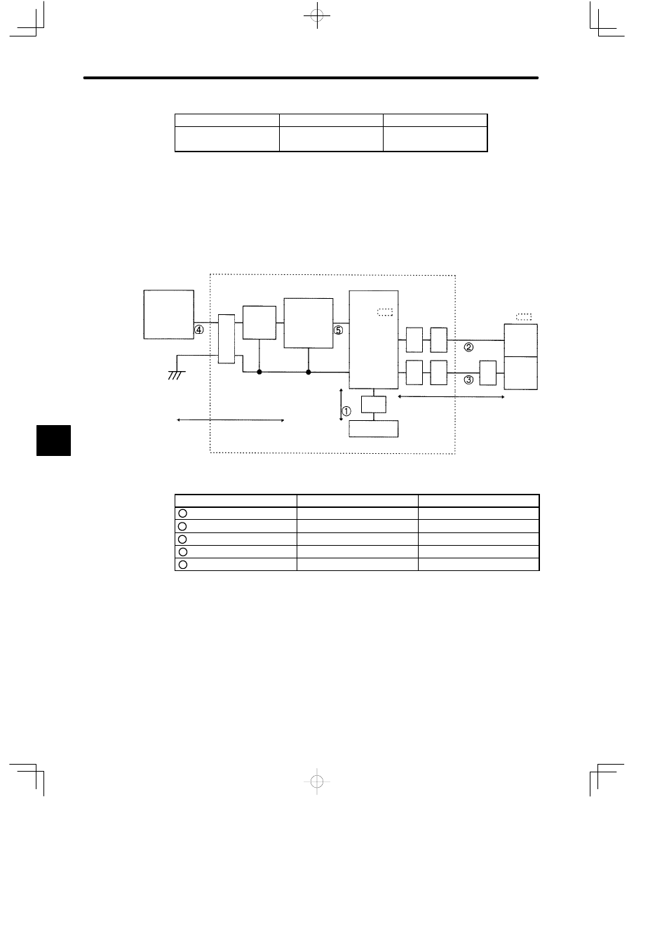
6.2.9 Wiring Examples
The following diagram shows the wiring conditions conforming to EMC Directive. The noise
filter and the core are shown in the diagram.
Power Supply
200 VAC
Single-phase
Clamp
Core
Core
Clamp
Clamp
Core
2 m (78.7 in)
5 m (196.8 in)
Servomotor
Motor
Encoder
FG
Clamps: Fix and ground the cable shield using a piece of conductive metal.
Clamp
Controller
Power Supply
AC/DC
Output: 24 VDC
Noise
Filter
CN1
CN2
FG
U, V, W
, GND
24 VDC
SGDF-
SERVOPACK
Earth Plate/Shield Box
SGMM-
Symbol
Name
Specification
1
Controller cable
Shield cable (0.5 m)
2
Motor cable
Shield cable (5 m)
3
Encoder cable
Shield cable (5 m)
4
AC Line cable
Shield cable (2 m)
5
DC Line cable
Shield cable (0.5 m)
6