Input /p-con cn1-*1 – Yaskawa Sigma Mini User Manual
Page 56
APPLICATIONS
2.2.1 Speed References cont.
— 2-12 —
Using /P-CON Signal:
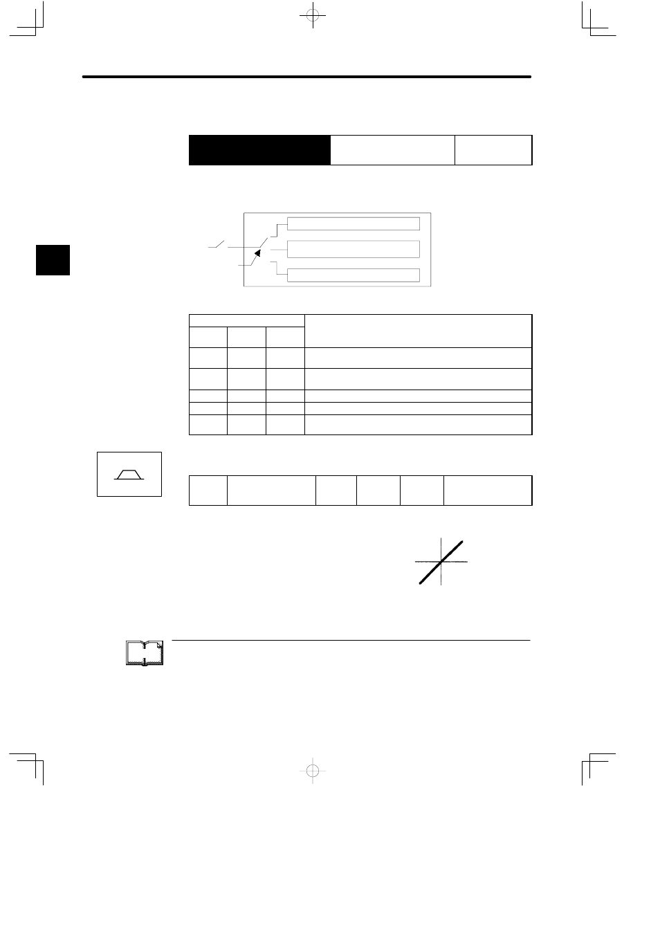
→ Input /P-CON CN1-*1
Proportional Control, etc.
For Speed/Torque
Control and
Position Control
The function of input signal /P-CON changes with the memory switch setting.
Servopack
Switching between P control and PI control
Switching between zero-clamp enabled mode and
zero-clamp disabled mode
Changing rotation direction
Memory
switch
/P-CON
Memory Switch
Cn-02
Bit 2
Cn-01
Bit B
Cn-01
Bit A
Meaning of /P-CON Signal
0
0
0
Switching between proportional (P) control and
proportional/integral (PI) control
0
0
1
Switching between zero-clamp enabled/disabled mode
(for speed/torque control only)
0
1
0
Not used (for speed/torque control only)
0
1
1
Not used (do not set)
1
---
---
Changing the direction of rotation during contact input speed
control
Adjust the speed reference gain using the following parameter.
Cn-03
VREFGN Speed
Reference Gain
Unit:
(min
−1
)/V
Setting
Range: 0
to 2162
Factory
Setting:
500
For Speed/Torque
Control
This parameter is for speed/torque control only.
Sets the voltage range for speed reference input
V-REF. Sets this parameter according to the out-
put form of the host controller or external circuit.
The factory setting is as follows:
Rated speed (3000 min
−1
)/6 V = 500
TERMS
Zero-clamp function
This function is used for a system in which the host controller does not form a position loop.
In this case, the stopping position may shift even if a speed reference is set to 0. If the zero-
clamp function is turned ON, a position loop is internally formed so that the stopping position
is firmly “clamped.”
2
Speed/Torque
Reference
speed (min
−1
)
Set this slope.
Reference
voltage (V)