Yaskawa Sigma Mini User Manual
Page 270
— C-5 —
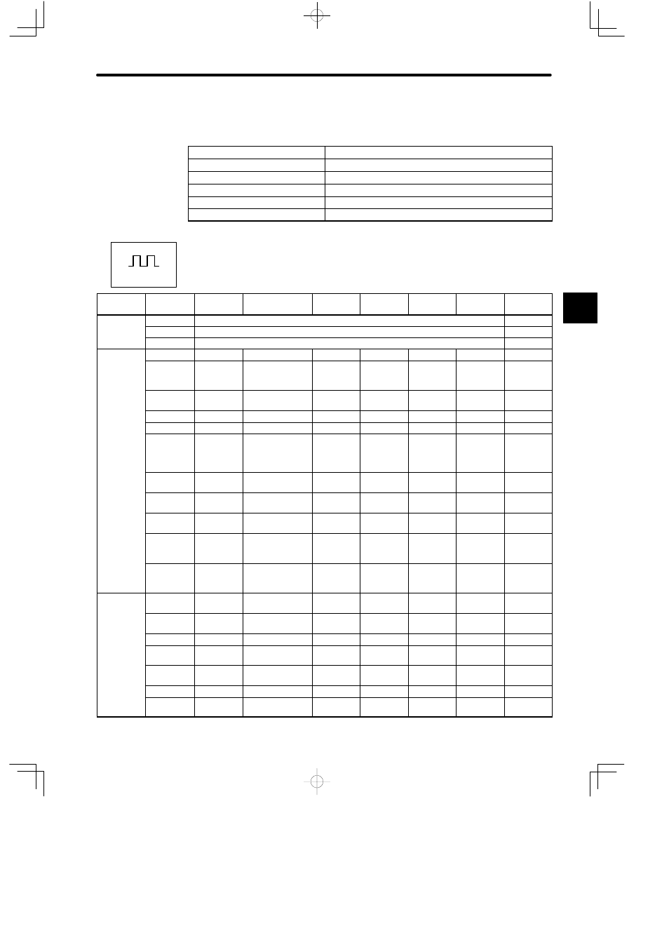
Output Signal Selection (Cn-2C) Setting Values
Select the functions of output signal CN1-8.
Setting Value
Function
0
ALM
1
/TGON
2
/BK
3
/V-CMP
4
/CLT
For Position Control
List of Parameters (Parameter Setting)
Category
Parameter
No.
Code
Name
Unit
Lower
Limit
Upper
Limit
Factory
Setting
Remarks
Cn-00
Not a parameter. (Cn-00 is used to select special mode for digital operator.)
Cn-01
Memory switch (see on page C-7)
See note 1
Cn-02
Memory switch (see on page C-7)
See note 1
Gain
R l
d
Cn-04
LOOPH
Speed loop gain Hz
1
2000
80
See note 2
Related
Constants
Cn-05
PITIME
Speed loop
integration time
constant
ms
2
10000
20
See note 2
Cn-1A
POSGN
Position loop
gain
1/s
1
500
40
Cn-1C
BIASLV
Bias
min
−1
0
450
0
Cn-1D
FFGN
Feed-forward
%
0
100
0
Cn-26
ACCTME
Position refer-
ence accelera-
tion/deceleration
time constant
100 µs
0
640
0
Cn-27
FFFILT
Feed-forward
reference filter
100 µs
0
640
0
Cn-08
TLMTF
Forward rotation
torque limit
%
0
Maximum
torque
Maximum
torque
Cn-09
TLMTR
Reverse rotation
torque limit
%
0
Maximum
torque
Maximum
torque
Cn-17
TRQFIL
Torque
reference filter
time constant
0.1 ms
0
250
4
Cn-28
CLMI
Forward/reverse
external torque
limit
%
0
Maximum
torque
100
Sequence
Related
C
Cn-07
SFSACC
Soft start time
(acceleration)
ms
0
10000
0
See note 4
e ated
Constants
Cn-23
SFSDEC
Soft start time
(deceleration)
ms
0
10000
0
See note 4
Cn-0B
TGONLV
Zero-speed level min
−1
1
20
Cn-12
BRKTIM
Base block wait
time
10 ms
0
50
0
Cn-15
BRKSPD
Brake wait
speed
min
−1
0
Maximum
speed
100
Cn-16
BRKWAI
Brake wait time
10 ms
10
100
50
Cn-1B
COINLV
Positioning
complete range
Reference
unit
0
250
7
C
Positions