3 positioning complete output, Output → /coin cn1-8 – Yaskawa Sigma Mini User Manual
Page 107
2.7Designing a Protective Sequence
— 2-63 —
This memory switch is used to enable or disable the
servo ON input signal /S-ON.
When external short-circuit wiring is omitted, set the
memory switch to “1.”
Setting
Meaning
0
Uses servo ON signal /S-ON
1
Does not use Servo ON signal /S-ON. (Servo is always ON.)
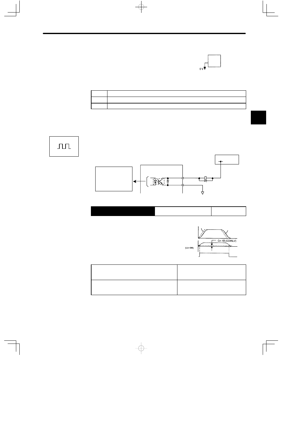
2.7.3 Positioning Complete Output
This section describes how to wire and use contact output-signal “positioning complete out-
put (/COIN).” This signal is output to indicate that Servomotor operation is complete.
CN1-8
CN1-3
/COIN
SG-COM
+24 V
Photocoupler output
Maximum operating voltage
per output: 30 VDC
Maximum output current
per output: 50 mA DC
Servopack
I/O power supply
Output → /COIN CN1-8
Positioning Complete Output
For Position
Control
This output signal indicates that motor operation is
complete during position control. The host controller
uses this signal as an interlock to confirm that position-
ing is complete.
ON
status:
Circuit between CN1-8 and CN1-3 is
closed.
CN1-8 is at low level.
Positioning is complete (position error is
below the preset value).
OFF
status:
Circuit between CN1-8 and CN1-3 is
open.
CN1-8 is at high level.
Positioning is not complete (position
error is over the preset value).
Preset Value: Cn-1B (positioning complete range)
Set the number of error pulses in the following parameter to adjust output timing of /COIN
(positioning complete output).
2
Servopack
When /S-ON is not used, this short-circuit
wiring can be omitted.
CN1-*1
(/S-ON)
Positions
Speed
Reference
Motor
Error
pulse
/COIN