Yaskawa Sigma Mini User Manual
Page 58
APPLICATIONS
2.2.2 Position References cont.
— 2-14 —
Note The signal logic for open collector output is as follows.
When Tr1 is ON
Equivalent to high level input
When Tr1 is OFF
Equivalent to low level input
Selecting Reference Pulse Form
Use the following memory switches to select the reference pulse form to be used:
→ Input PULS CN1-14
Reference Pulse Input
For Position Control
→ Input
/
PULS CN1-15
Reference Pulse Input
For Position Control
→ Input SIGN CN1-16
Reference Sign Input
For Position Control
→ Input
/
SIGN CN1-17
Reference Sign Input
For Position Control
The motor rotates at an angle proportional to the input pulse.
Cn-02 Bit 3
Reference Pulse Form
Selection
Factory
Setting: 0
For Position Control
Cn-02 Bit 4
Reference Pulse Form
Selection
Factory
Setting: 0
For Position Control
Cn-02 Bit 5
Reference Pulse Form
Selection
Factory
Setting: 0
For Position Control
Sets the form of a reference pulse that is externally
output to the Servopack.
Sets the pulse form according to the host controller
specifications.
Set also the input pulse logic in bit D of Cn-02.
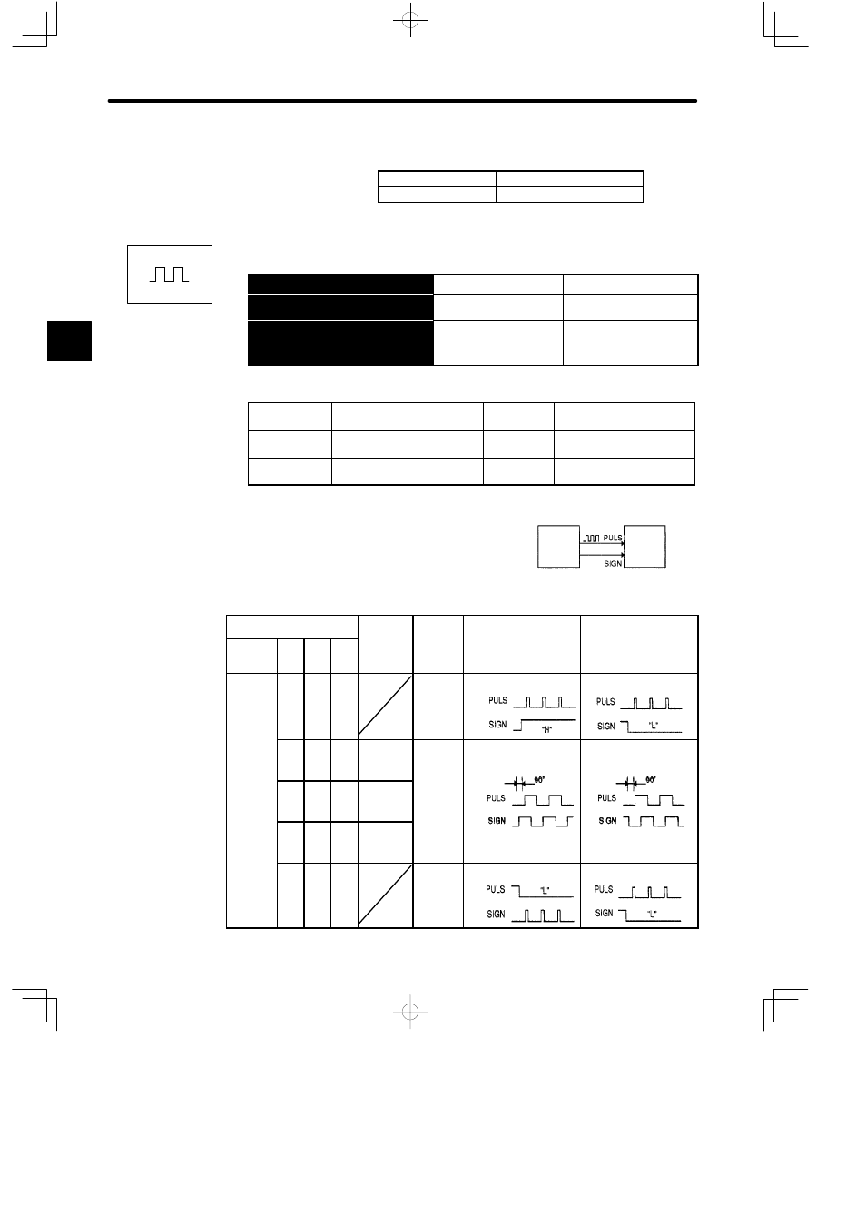
Cn-02
Input
Pulse
Refer-
ence
Motor Forward Run Motor Reverse Run
Bit D
Bit
5
Bit
4
Bit
3
Pulse
Multipli-
er
ence
Pulse
Form
Motor Forward Run
Reference
Motor Reverse Run
Reference
0
0
0
Sign +
pulse
train
0
0
1
0
¢
1
Two-
phase
pulse
0
(Posi-
tive
logic
0
1
1
¢
2
pulse
train
with
90°
og c
setting)
1
0
0
¢
4
90
phase
differ-
ence
0
0
1
CW
pulse +
CCW
pulse
2
Positions
Host
controller
Position
reference
pulse
Servopack
CN1-14
CN1-16