Yaskawa Sigma Mini User Manual
Page 21
BASIC OPERATION
1.2.2 Installing the Servomotorcont.
— 1-8 —
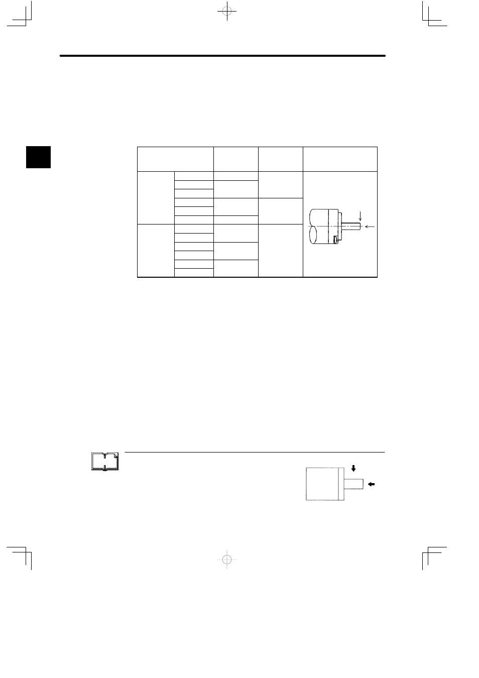
Allowable Load on Shaft End
Mechanical shock to the shaft end must be less than 490 m/s
2
and must be applied no
more than twice.
Design the mechanical system so that thrust load and radial load applied to the Servo-
motor shaft end during operation falls within the range shown in the following table.
Servomotor Model
SGMM-
Allowable
Radial Load
Fr [N(lb)]
Allowable
Thrust Load
Fs [N(lb)]
Reference Drawing
Standard
A1C31jj
34.1 (7.7)
14.7 (3.3)
A2C31jj
44.1 (9.9)
(
)
A3C31jj
(
)
B3CF1j
8 (1.8)
4.0 (0.90)
F
B5CF1j
(
)
(
)
Fr
B9CF1j
10 (2.2)
Fs
With Gears
A1C3JAjj
51.9 (11.7)
47.0 (10.5)
Fs
A2C3JAjj
(
)
(
)
A1C3JBjj
76.4 (17.2)
A2C3JBjj
(
)
A1C3JCjj
89.2 (20.1)
A2C3JCjj
(
)
Note a) The box (j) at the end of the model number is for the shaft specifications.
b) The allowable load is applied to the shaft end.
TERMS
Thrust load and radial load
Thrust load (Fs): Shaft-end load applied parallel to the
centerline of a shaft
Radial load (Fr): Shaft-end load applied perpendicular to
the centerline of a shaft
Motor
Shaft end
Fr
Fs
1