2 servo on input signal, Input /s-on cn1-*1 – Yaskawa Sigma Mini User Manual
Page 106
APPLICATIONS
2.7.2 Servo ON Input Signal
— 2-62 —
Normally, this signal terminal need not be wired. This is because an external circuit is normal-
ly formed so that servo power is turned OFF when servo alarm is output. Alarm state is auto-
matically reset when servo power is turned ON next time.
Alarm state can be reset using the Digital Operator.
When an alarm occurs, always eliminate the cause before resetting the alarm state. Refer to
5.2.1 Troubleshooting Problems with Alarm Display for details on how to troubleshoot the
system when an alarm arises.
2.7.2 Servo ON Input Signal
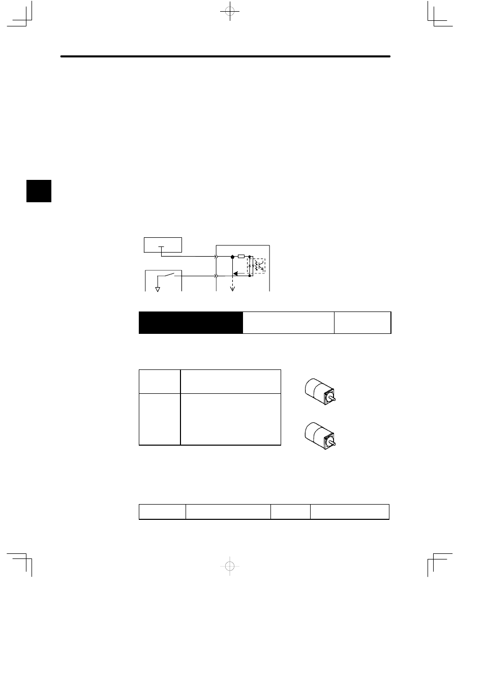
This section describes how to wire and use contact input signal “servo ON (/S-ON).” Use this
signal to forcibly turn OFF the Servomotor from the host controller.
5 mA
+24 V
+24 VIN
CN1-9
4.7 kΩ
/S-ON
CN1-
*1
0 V
Servopack
Photo-
coupler
Host controller
I/O power supply
→ Input /S-ON CN1-*1
Servo ON
For Speed/Torque
Control and
Position Control
This signal is used to turn the motor ON or OFF.
ON: CN1-*1
is at low
level
Turns ON the motor. This is normal
operation state (called “servo ON
state”).
OFF: CN1-*1
is at high
level
Turns OFF the motor. This is inop-
erable state (called “servo OFF
state“).
If the servo is turned OFF during
motor operation, the motor is decel-
erated to a stop by applying dynam-
ic brake.
Note
Do not use the /S-ON signal to start or stop the motor. Always use an input reference to start
and stop the motor.
If the /S-ON signal is not to be used, set the following memory switch to 1.
Cn-01 Bit 0
Use of Servo ON Input Signal Factory
Setting: 0
For Speed/Torque Control
and Position Control
2
Servo ON
Motor is ON
Motor is
operated
according to
input signals.
Servo OFF
Motor is OFF
Motor
cannot run.