Yaskawa Sigma Mini User Manual
Page 38
1.4Conducting a Test Run
— 1-25 —
Check input signals.
Using the Digital Operator, check the input signal wir-
ing in monitor mode. For the checking method, refer to
3.1.6 Operation in Monitor Mode.
Turn each connected signal line ON and OFF to check
that the monitor bit display changes accordingly as
shown below.
Input Signal
ON/OFF
Monitor Bit Display
High level or open
OFF
Not lit
0 V level
ON
Lit
If the signal lines below are not wired correctly, the Servomotor fails to rotate. Always wire
them correctly. (If signal lines are not to be used, short them as necessary.) The signal lines
can be shorted externally by setting the memory switch.
Signal
Symbol
Connector
Pin No.
Description
/S-ON
CN1-1
Servo is turned ON when this input signal is at 0 V. However,
leave the servo in OFF status.
Turn ON servo (motor).
Turn ON the servo as follows:
Check that no reference has been input.
• Speed/torque control:
V-REF and T-REF are at 0 V.
• Position control:
PULS and SIGN are fixed.
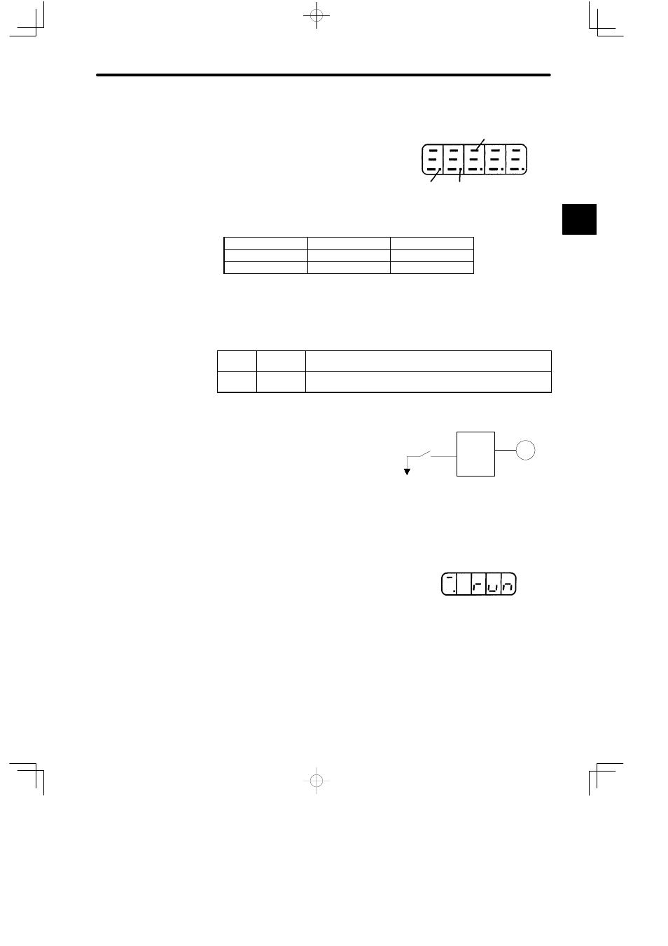
Set /S-ON to 0 V. If normal, the motor is turned
ON and the Digital Operator displays the data as
shown in the figure. If an alarm display appears,
take appropriate action as described in Appendix
D List of Alarm Displays.
Operate by reference input.
The operating procedure differs according to the Servopack control mode used.
1
Internal status bit display
(Un-05, Un-06)
Example of
Un-05
/S-ON
/P-CON
/CL
Servopack
Servomotor
Turn the servo ON.
/S-ON
CN1-1
0V
Display when Servo Is
Turned ON