30 w – Yaskawa Sigma Mini User Manual
Page 193
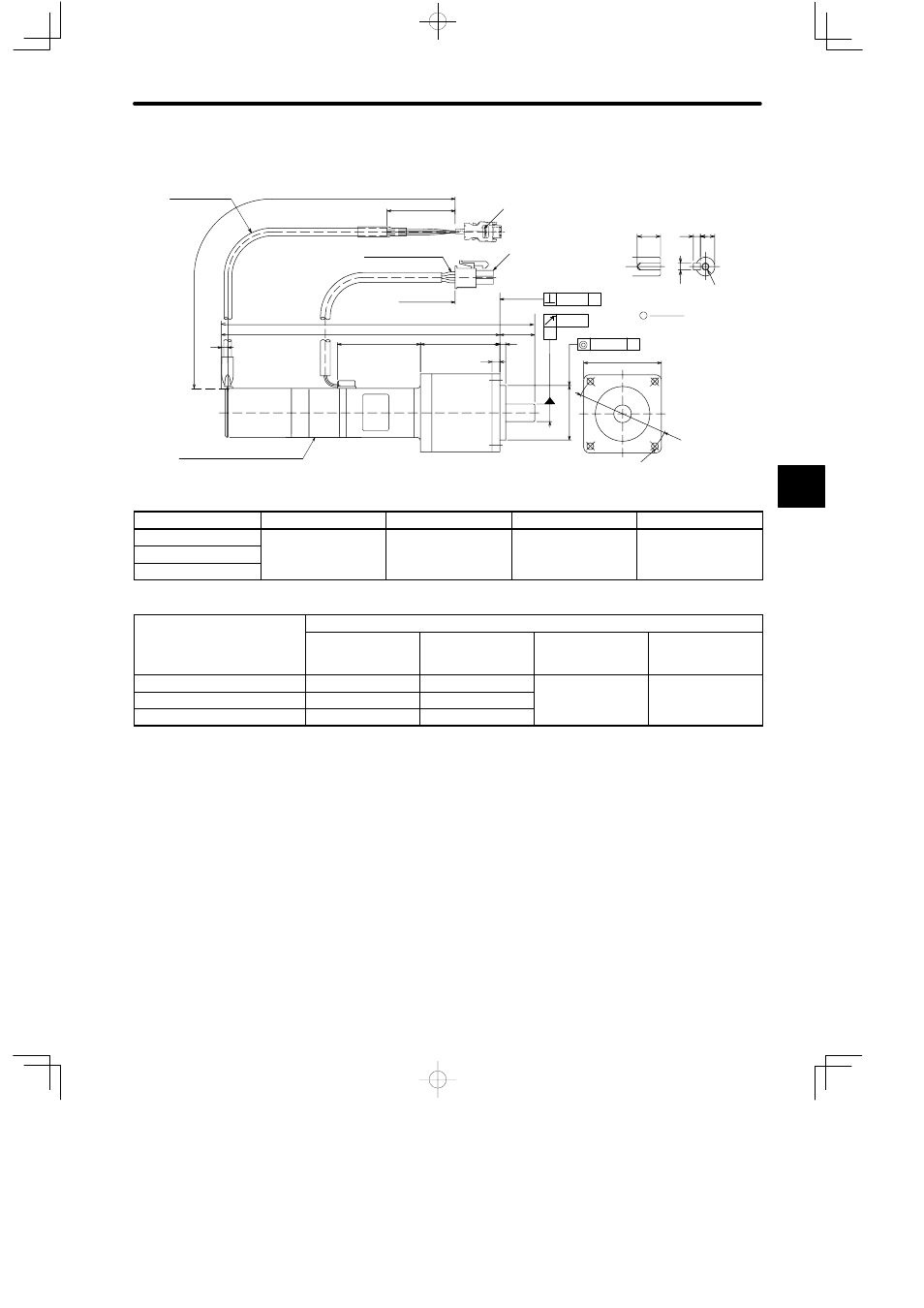
4.4Servo Drive Dimensional Drawings
— 4-43 —
• 30 W
4 x φ3.4 (0.13) dia.
3
L
L1
L2
4
A
A
A
φ 0.05
0.04
0.06
11 (0.43)
7.2 (0.28)
j
40
φ 47 (1.85)
Holding brake (non-excitation operation)
Voltage: 24 VDC, capacity: 3 W max. (Reference)
90 VDC
35 (1.38)
300 (11.81) ±30 (1.18)
Encoder connector
Motor connector
18 (0.71)
3
(0.12)
AWG24,UL10095 or UL3266
Motor Leads
UL20276
Encoder Leads
M3 tap screw,
depth: 6 (0.24)
Shaft end
(with key and tap
j
= 6)
a
3
(0.12)
3 (0.12)
(0.0024)
(0.0016)
(φ 0.0020)
(A)
(B)
(0.12)
(A): φ 9
0
−0.015
(φ 0.354
−0.0003
−0.0005
)
(B): φ 28
0
−0.021
(φ 1.102
−0.0003
−0.0005
)
(0.16)
300 (11.81)
±30 (1.18)
Model SGMM-
L mm (in)
L1 mm (in)
L2 mm (in)
Approx. Mass (g)
A3S3J1jj
167.5 (6.59)
149.5 (5.89)
52.7 (2.07)
545
A3S3J2jj
(
)
(
)
(
)
A3S3J3jj
Model SGMM-
Reduction Gears
Gear Ratio
Allow-able Radial
Load
N (lb)
Allow-able Thrust
Load
N (lb)
Lost Motion
A3S3J1jj
1/5
68.7 (15.45)
58.8 (13.23)
0.5 (deg)
A3S3J2jj
1/16
147 (33.07)
(
)
( g)
A3S3J3jj
1/25
186 (41.85)
Note
1) The detector uses a 2048 P/R incremental encoder.
2) The keyway complies with JIS B 1301-1976 (precision). A straight key is supplied (types
with key only).
3) The allowable load is applied to the shaft end.
4) The electromagnetic brake is only to hold the load in position and cannot be used to stop
the motor.
4