3 encoder output – Yaskawa Sigma Mini User Manual
Page 61
2.2Setting Parameters According to Host Controller
— 2-17 —
Use this signal to clear the error counter from the host controller.
Bit A of memory switch Cn-02 can be set so that the error counter is cleared only once when
the leading edge of an input pulse rises.
Cn-02 Bit A
Error Counter Clear Signal
Selection
Factory
Setting: 0
For Position Control
Selects the pulse form of error counter clear signal CLR.
Setting
Meaning
0
Clears the error counter when the CLR
signal is set at high level. Error pulses
do not accumulate while the signal
remains at high level.
Cleared state
1
Clears the error counter only once when
the rising edge of the CLR signal rises.
Cleared only once at this point
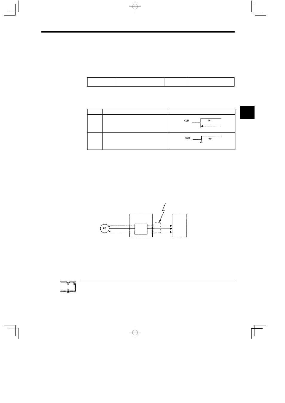
2.2.3 Encoder Output
Encoder output signals divided inside the Servopack can be output externally. These signals
can be used to form a position control loop in the host controller.
Servomotor
encoder
Servopack
Frequency
dividing
circuit
Host
controller
This output is
explained here.
Phase A
Phase B
Phase C
CN2
CN1
TERMS
Divided (or dividing)
“Dividing” means converting an input pulse train from the encoder mounted on the motor
according to the preset pulse density and outputting the converted pulse. The unit is pulses
per revolution.
2