Yaskawa Sigma Mini User Manual
Page 31
BASIC OPERATION
1.3.3 Examples of Connecting Host Controllerscont.
— 1-18 —
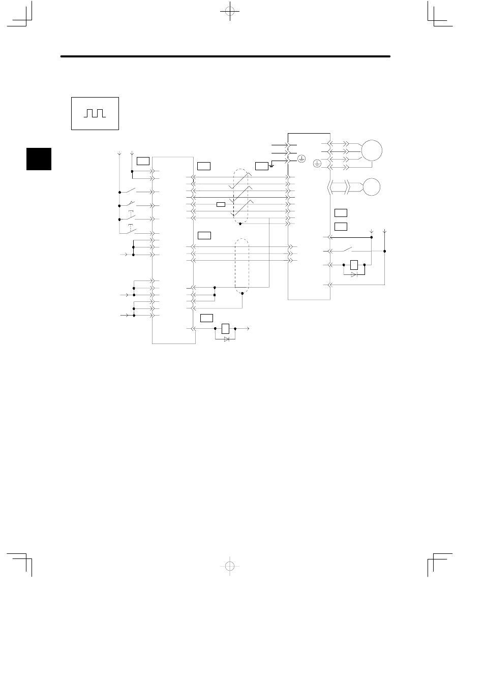
Example of Connecting to GL-series B2813 Positioning Module
Servopack for Position Control
CN1
24
15
22
21
28
38
17
14
16
17
18
19
13
20
6
19
15
1
2
3
20
14
16
18
9
1
7
3
1
33
20
25
3
2
45
46
47
48
49
50
10
11
12
*1 The ALM signal is output for approximately
two seconds when the power is turned ON.
Consider this when desigining the power ON
sequence.
Use the ALM signal to operate the alarm
detection relay (Relay 1Ry) and turn OFF the
power supply to the Servopack.
STOP
START
+24 V
0
24
V
Yaskawa
JAMSC-B2833
Servomotor
Servopack
SERVO
NORMAL
DECEL LS
PULSE
/PULSE
SIGN
/SIGN
+12 V
CLR
0 V
/PA
/PB
/PC
0 V
0 V
0 V
FG
CN1
CN1
CN2
CN2
CN1
CN2
+12 V
+12 V
+5 V
0V
1Ry
2Ry
36
1kΩ
PULSE
/PULSE
SIGN
/SIGN
CLR
/CLR
SG
FG
+24 VIN
/S-ON
ALM
SG-COM
+24 V 0
24
V
PAO
PBO
PCO
23
ALARM
*1
DC24V
GND
U
V
W
M
PG
1
Positions