2 troubleshooting problems with no alarm display – Yaskawa Sigma Mini User Manual
Page 233
5.2 Error Diagnosis and Troubleshooting
— 5-13 —
5.2.2 Troubleshooting Problems With No Alarm Display
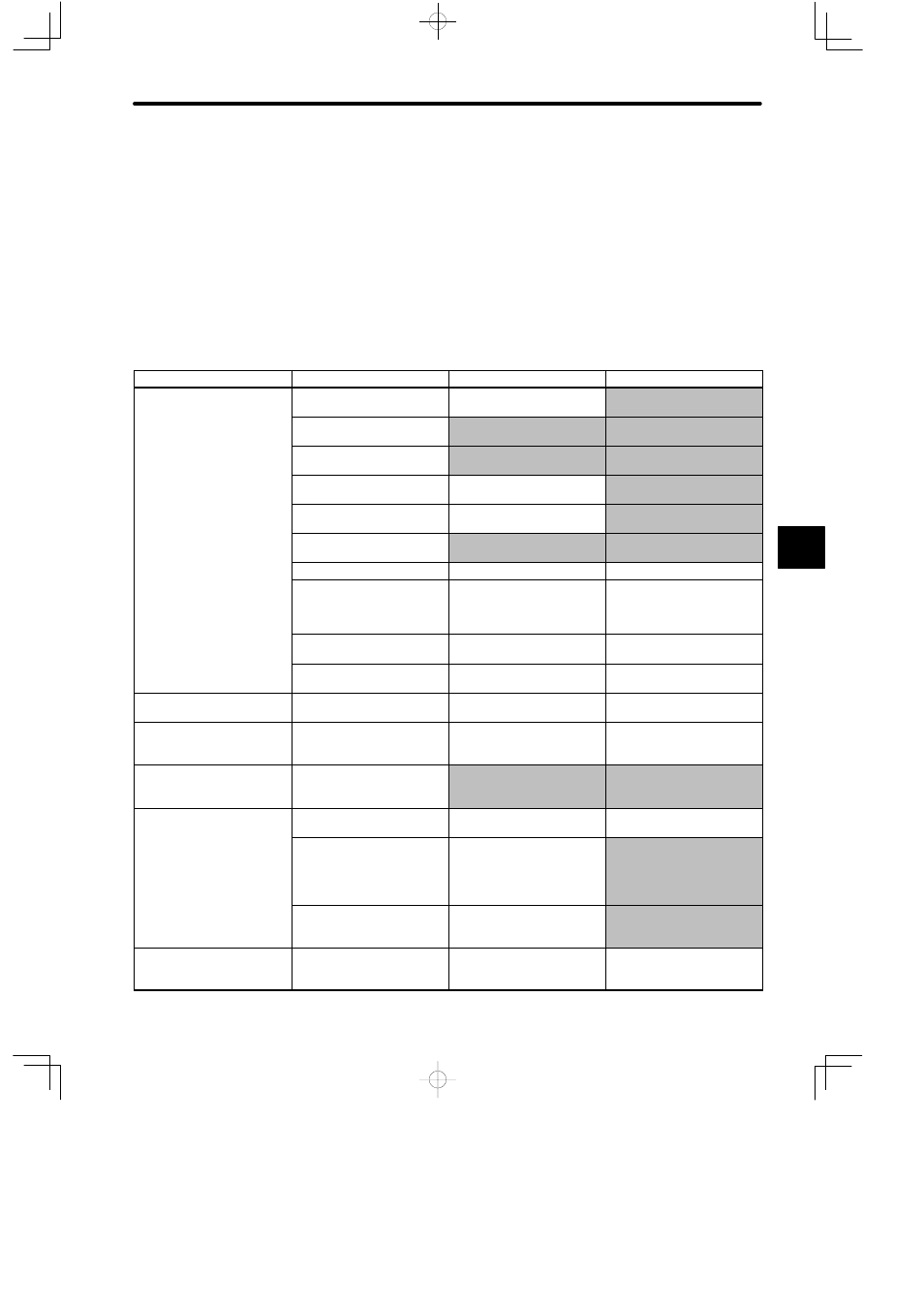
Refer to the following table to identify the cause of a problem that causes no alarm display and
take the remedy described.
Turn OFF the servo system power supply before commencing the procedures indicated with
shading.
Contact your Yaskawa representative if the problem cannot be solved by the described pro-
cedures.
Symptom
Cause
Inspection
Remedy
Servomotor does not start
Power not connected
Check voltage across
24 VDC and GND.
Correct the power circuit.
Loose connection
Check terminals of
connectors (CN1, CN2).
Tighten any loose parts.
Connector (CN1) external
wiring incorrect
Check connector (CN1)
external wiring
Refer to connection diagram
and correct wiring.
Servomotor or encoder
wiring disconnected.
Reconnect wiring
Overloaded
Run under no load.
Reduce load or replace with
larger capacity Servomotor.
Speed/position references
not input
Check input pins.
Correctly input
speed/position references.
/S-ON is turned OFF
Cn-01 bit 0 is 0.
Turn /S-ON input ON.
/P-CON input function
setting incorrect
Check parameters Cn-01
bits A, B.
Refer to 2.2.1 Speed
References and set
parameters to match
application.
Reference pulse mode
selection incorrect.
Refer to 2.2.2 Position
References.
Select correct parameters
Cn-02 bits 3, 4, 5.
/CLR input is turned ON
Check status of error
counter clear input.
Turn /CLR input OFF.
Servomotor moves
instantaneously, then stops
Servomotor or encoder
wiring incorrect.
Refer to 2.8 Special Wiring
and correct wiring.
Suddenly stops during
operation and will not restart
Alarm reset signal
(/ALMRST) is turned ON
because an alarm occurred.
Remove cause of alarm.
Turn alarm reset signal
(/ALMRST) from ON to OFF.
Servomotor speed unstable
Wiring connection to
Servomotor defective
Check connection of power
lead (phases U, V, and W)
and encoder connectors.
Tighten any loose terminals
or connectors.
Servomotor vibrates at
approximately 200 to
Speed loop gain value too
high.
Reduce speed loop gain
(Cn-04) preset value.
app o
ate y 00 to
400 Hz.
Speed/position reference
input lead too long.
Minimize length of
speed/position reference
input lead, with impedance
not exceeding several
hundred ohms
Speed/position reference
input lead is bundled with
power cables.
Separate reference input
lead at least 30 cm from
power cables.
High rotation speed
overshoot on starting and
stopping.
Speed loop gain value too
high.
Reduce speed loop gain
(Cn-04) preset value.
5