A.51 – Yaskawa Sigma Mini User Manual
Page 226
INSPECTION AND MAINTENANCE
5.2.1 Troubleshooting Problems with Alarm Display
— 5-6 —
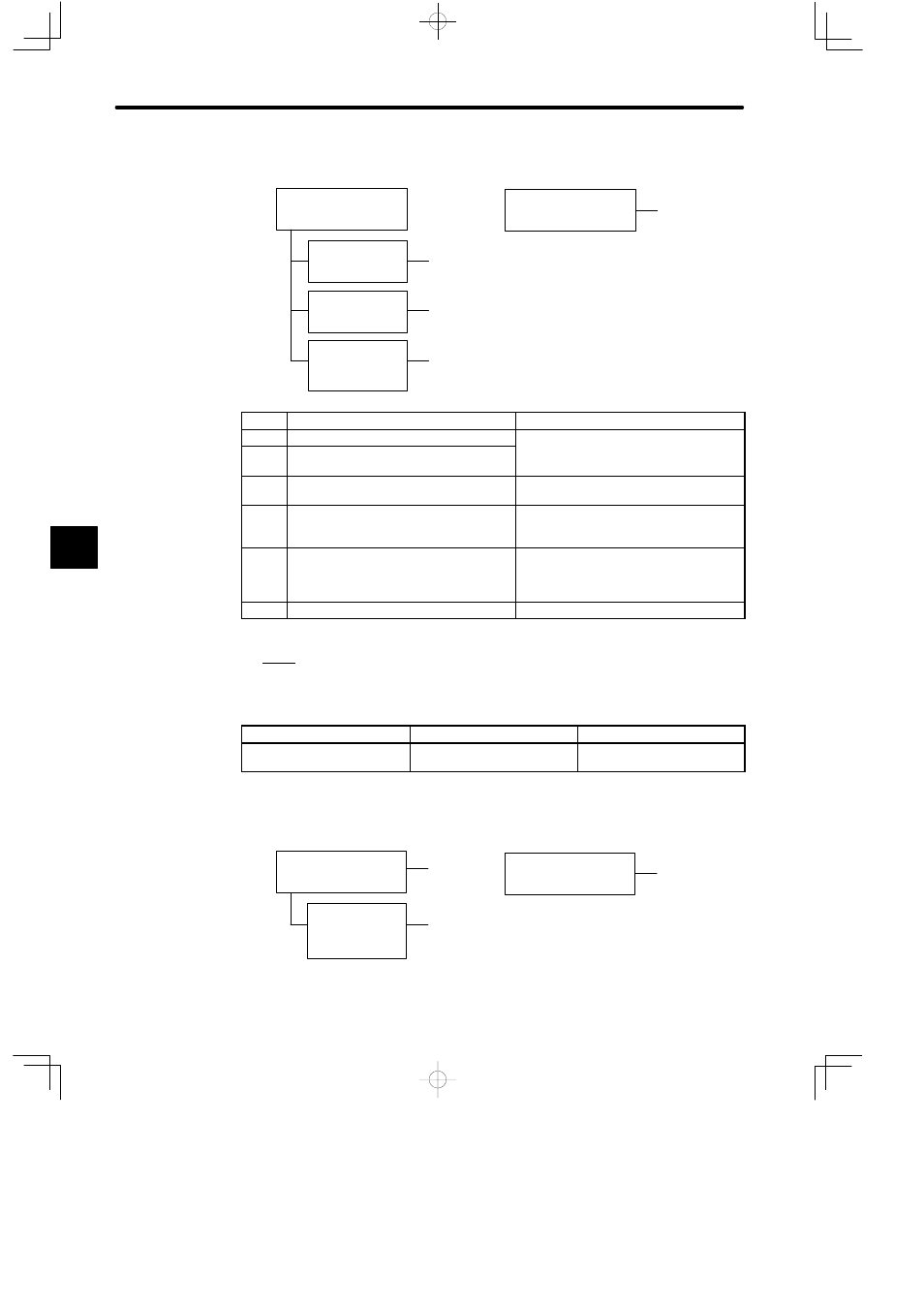
Status when Alarm Occurred
A
During Servomotor
operation
Overflow during
high-speed opera-
tion
No feedback pulse
returned after refer-
ence pulse input
Normal operation but
overflow when large
reference input
At power ON
B
,
F
C
,
D
,
E
F
Cause
Remedy
A
Servomotor wiring incorrect.
Check and correct wiring. (Check phase-A,
B C
l
CN2 )
B
Encoder wiring incorrect (disconnection,
short circuit, power supply, etc.)
g (
p
,
-B, -C pulses correct at CN2.)
C
Servopack adjustment incorrect
Increase speed loop gain (Cn-04) and/or
position loop gain (Cn-1A).
D
Servomotor overloaded
Reduce load torque and load moment of
inertia. Otherwise, replace with larger
capacity Servomotor.
E
Position reference pulse frequency too
high
• Decrease reference pulse frequency.
• Use smoothing function.
• Change electronic gear ratio.
F
Circuit board (1PWB) defective.
Replace Servopack.
5. A.51
Display and Outputs
Digital Operator Display
Alarm Name
Alarm Output
A.51
Overspeed
Output transistor is OFF
(alarm state)
Status when Alarm Occurred
A
, B, C, D
When servo ON (S-ON)
signal turned ON
During high-speed
Servomotor rotation
after reference in-
put
Alarm detected at
110% max. speed
At power ON
D
A
, B, C, D
5