9 reference pulse input filter selection function – Yaskawa Sigma Mini User Manual
Page 81
2.2Setting Parameters According to Host Controller
— 2-37 —
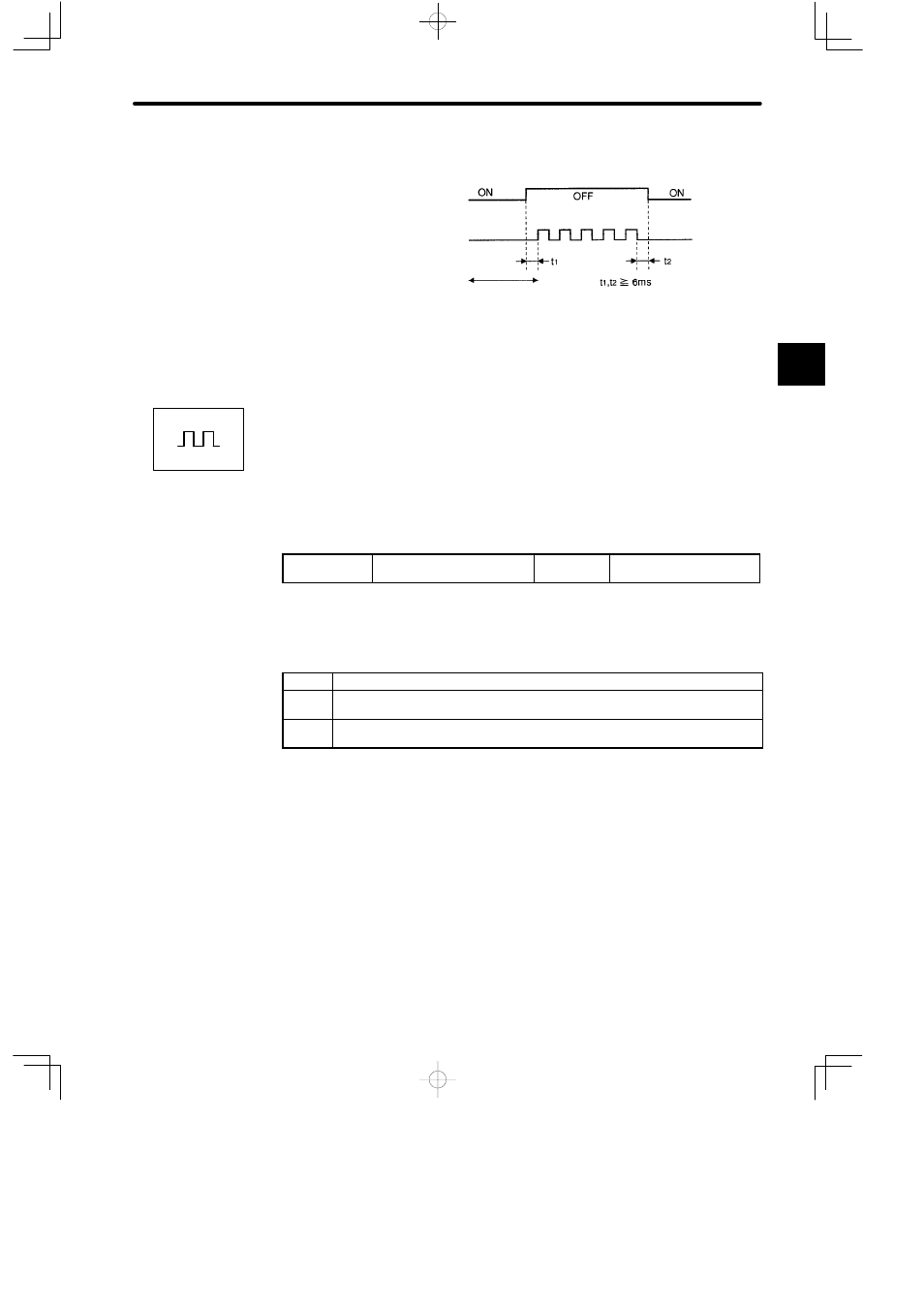
Relationship between INHIBIT Signal and Reference Pulse
/INHIBIT signal
(/P-CON)
Reference pulse
Input reference pulses
are not counted
during this period.
2.2.9 Reference Pulse Input Filter Selection Function
The reference pulse input filter selection function selects a reference pulse input filter inside
the Servopack according to the output form of reference pulses from the host controller.
How to Use Reference Pulse Input Filter
Set the following memory switch according to the output form of reference pulses from the
host controller:
Cn-02 Bit F
Reference Pulse Input Filter
Selection Function
Factory
Setting: 0
For Position Control
Sets the memory switch according to the output form (line driver or open collector) of refer-
ence pulses from the host controller.
Setting
Meaning
0
Output form of reference pulses from host controller: Line driver output (maximum
frequency of reference pulse: 450 kpps)
1
Output form of reference pulses from host controller: Open collector output
(maximum frequency of reference pulse: 200 kpps)
For open collector output, the wire length must be as short as possible (3 m max.).
Note
If a reference greater than 200 kpps is output, the reference pulses may be miscounted due to
noise even when the reference pulse is an open-collector output. Miscounting will result in
positioning errors. Make sure that wiring is correct and always set memory switch Cn-02 bit F
to 0.
2
Positions