7 designing a protective sequence, 1 servo alarm output, Output → alm cn1-7 – Yaskawa Sigma Mini User Manual
Page 104: Output → sg-com cn1-3
APPLICATIONS
2.7.1 Servo Alarm Output
— 2-60 —
2.7
Designing a Protective Sequence
This section describes how to use I/O signals from the Servopack to form a protective
sequence for safety purposes.
2.7.1 Servo Alarm Output
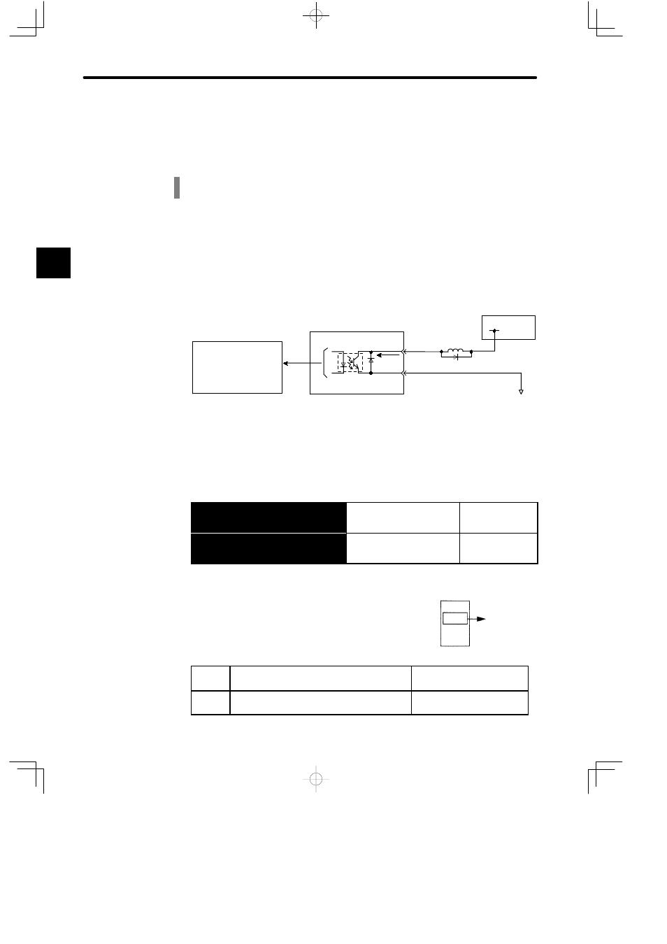
The following diagram shows the basic wiring for alarm output signals.
Servopack
CN1-7
CN1-3
ALM
SG-COM
I/O power supply
+24 V
Photocoupler
Photocoupler output
Maximum operating voltage
per output:30 VDC
Maximum output current
per output: 50 mA DC
MAX 50 mA
Provide an external I/O power supply separately. There are no DC power available from Ser-
vopack for output signals.
Contact Output Signal ALM
Output → ALM CN1-7
Servo Alarm Output
For Speed Torque
and Position
Control
Output → SG-COM CN1-3
Signal Ground for Servo
Alarm Output
For Speed Torque
andPosition
Control
Signal ALM is output when the Servopack detects an alarm.
Form an external circuit so that the alarm output
(ALM) turns OFF the Servopack.
ON
status:
Circuit between CN1-7 and CN1-35 is closed.
CN1-7 is at low level.
Normal state
OFF
status:
Circuit between CN1-7 and CN1-35 is open.
CN1-7 is at high level.
Alarm state
2
Turns OFF the
power.
ALM output
Alarm
detection
Servopack