Yaskawa Sigma Mini User Manual
Page 189
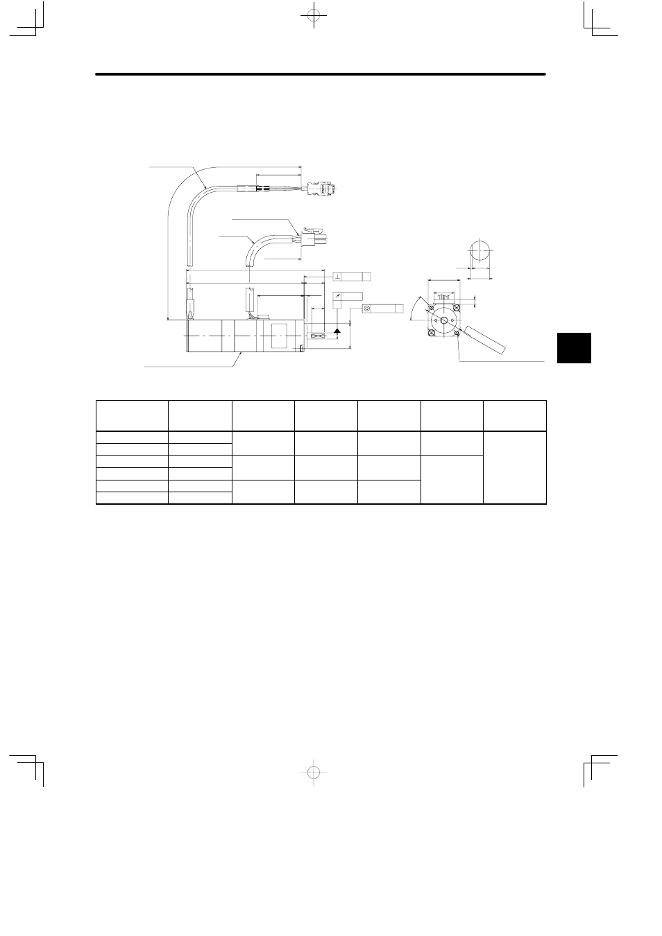
4.4Servo Drive Dimensional Drawings
— 4-39 —
Incremental Encoders with Brakes (Type SGMM-jjS31jC)
• 10 W, 20 W
A
0.02
φ 0.04
A
0.04
A
2 x M3 tap screws, depth: 5 (0.20)
)
j
25 (0.98)
2.5
16
10
0.5
Shaft end
(with flat seat)
L2
16 (0.63)
35 (1.38)
Encoder Leads, UL20276
4
4.5
Protective Tube,
5 mm (0.20) dia.,
black
Holding brake (non-excitation operation)
Voltage: 24 VDC, capacity: 3 W max.
L
L1
Motor Leads, AWG24, UL10095
300 (11.81) ±30 (1.18)
300 (11.81)
±30 (1.18)
(0.63)
(0.10)
(0.39)
(0.0015)
(0.0008)
(φ 0.0018)
(A): φ 5
0
−0.008
(0.197
−0.0001
−0.0005
)
(B): φ 20
0
−21
(φ 0.79
0
−0.83
)
(A)
(A)
(B)
(0.02) (0.18)
(0.16)
45
°
φ 28 (φ 1.10)
Type SGMM-
Shaft
L mm (in)
L1 mm (in)
L2 mm (in)
Allowable
Radial Load N
(lb)
Allow-able
Thrust Load
N (lb)
A1S312C
No flat seat
94.5 (3.72)
78.5 (3.09)
26.5 (1.04)
34.3 (7.7)
14.7 (3.3)
A1S313C
With flat seat
(
)
(
)
(
)
(
)
(
)
A2S312C
No flat seat
108.5 (4.27)
92.5 (3.64)
36.5 (1.44)
44.1 (9.9)
A2S313C
With flat seat
(
)
(
)
(
)
(
)
A3S312C
No flat seat
128.5 (5.06)
112.5 (4.43)
46.5 (1.83)
A3S313C
With flat seat
(
)
(
)
(
)
Note
1) The detector uses a 2048 P/R incremental encoder.
2) The allowable load is applied to the shaft end.
4