A.1 sigma-series ac servopack gain adjustment, A.1 σ -series ac servopack gain adjustment – Yaskawa Sigma Mini User Manual
Page 248
SERVO ADJUSTMENT
A.1.1 Σ-Series AC Servopacks and Gain Adjustment Methods
— A-2 —
A.1 Σ-Series AC Servopack Gain Adjustment
This section provides some basic information required to adjust the servo system.
A.1.1 Σ-Series AC Servopacks and Gain Adjustment Methods
1) The main parameters changed by the customer to adjust the servo system include the
following:
• Cn-04 (Speed Loop Gain)
• Cn-05 (Speed Loop Integration Time Constant)
• Cn-17 (Torque Reference Filter Time Constant)
• Cn-1A (Position Loop Gain)
In a Servopack for speed control (where speed references are applied as analog volt-
ages), the position loop is controlled by the host controller, so the position loop gain is
normally adjusted at the host controller.
If adjustment is not possible at the host controller, the same adjustment can be achieved
using Cn-03 (Speed Reference Gain), but the Servomotor may not reach maximum
speed for some preset values of this parameter.
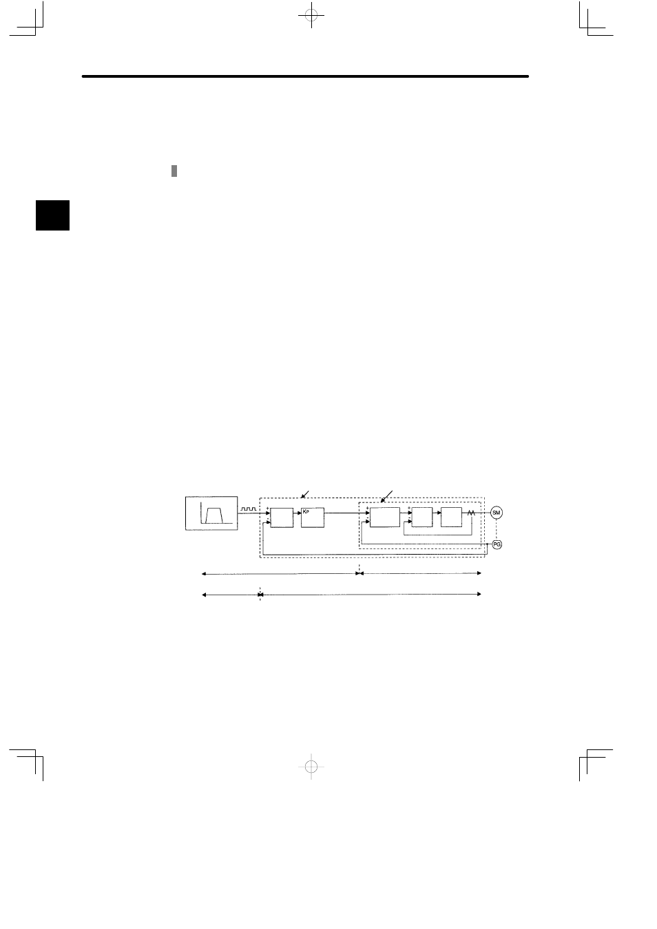
A simple block diagram of the servo system is shown below.
Speed Speed
Pattern
Time
Pulse
Train
Position-control Servopack Speed-control Servopack
Error
Count-
er
Position Control Loop
(D/A
Convert-
er)
Analog Voltage
Speed Control Loop
Speed
Control
Section
Current
Control
Section
Power
Con-
verter
Motor
Encoder
Using Servopack for
Speed Control
Host Controller (supplied by customer)
Servopack
Using Servopack for
Position Control
Host Controller
(supplied by
customer)
Servopack
Kp: Position Loop Gain
Kv: Speed Loop Gain
Ti: Integration Time Constant
Note: A position-control Servopack has no D/A converter for speed reference
output. This conversion is handled by internal calculations.
A