5 minimum parameters and input signals – Yaskawa Sigma Mini User Manual
Page 43
BASIC OPERATION
1.4.5 Minimum Parameters and Input Signals
— 1-30 —
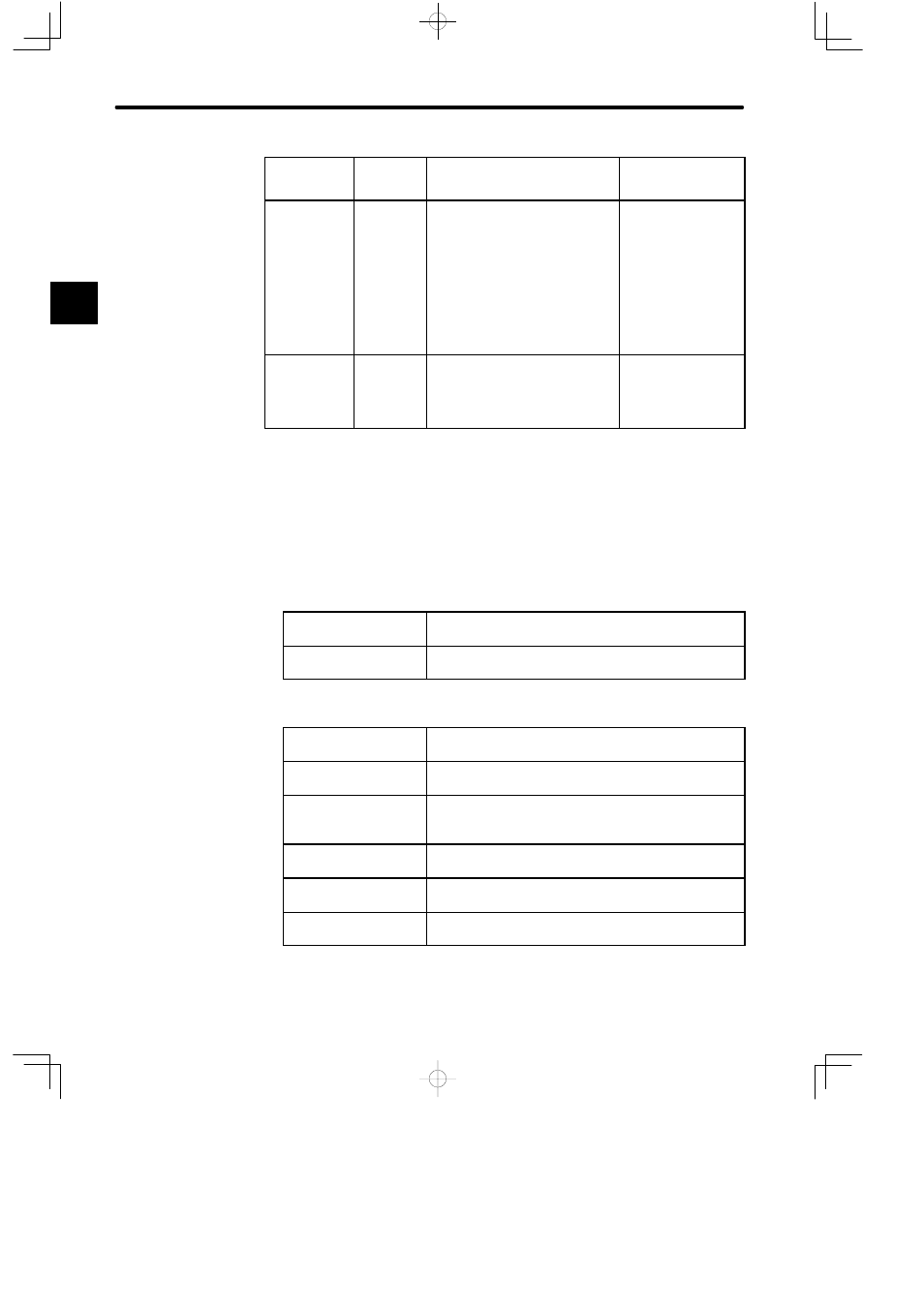
Reference
from Host
Controller
Check
Items
Check Method
Review Items
Jogging
(constant-
speed refer-
ence input from
host controller)
Motor
speed
Check the Servomotor speed as fol-
lows:
D
Use the speed monitor (Un-00) of
the Digital Operator.
D
Run the Servomotor at low
speed. For example, input a
speed reference of 60 min
−1
and
check that the Servomotor makes
one revolution per second.
Check whether the
speed reference gain
value (parameter
Cn-03) is correct.
Simple posi-
tioning
Number of
Servomotor
revolutions
D
Input a reference equivalent to
one Servomotor revolution and
visually check that the
Servomotor shaft makes one
revolution.
Check whether the di-
viding ratio count (pa-
rameter Cn-0A) is cor-
rect.
1.4.5 Minimum Parameters and Input Signals
Minimum Parameters Required for Test Run
For details on how to set each parameter, refer to 3.1.5 Operation in Parameter Setting Mode.
Servopack for Speed/Torque Control
Cn-03
Speed reference adjustment gain
Refer to 2.2.1 Speed References.
Cn-0A
Encoder pulse dividing ratio
Refer to 2.2.3 Encoder Output.
Servopack for Position Control
Cn-02 bits 3,4,5
Reference pulse form selection
Refer to 2.2.2 Position References.
Cn-02 bit D
Logic of reference pulse
Refer to 2.2.2 Position References.
Cn-02 bit F
Reference pulse output form
Refer to 2.2.9 Reference Pulse Input Selection Func-
tion.
Cn-0A
Encoder pulse dividing ratio
Refer to 2.2.3 Encoder Output.
Cn-24
Electronic gear ratio (numerator)
Refer to 2.2.5 Electronic Gear.
Cn-25
Electronic gear ratio (denominator)
Refer to 2.2.5 Electronic Gear.
After changing the Cn-02 setting, always turn OFF the power, then turn ON again.
Turning ON the power again validates the new settings.
1