Yaskawa Sigma Mini User Manual
Page 265
LIST OF I/O SIGNALS
— B-4 —
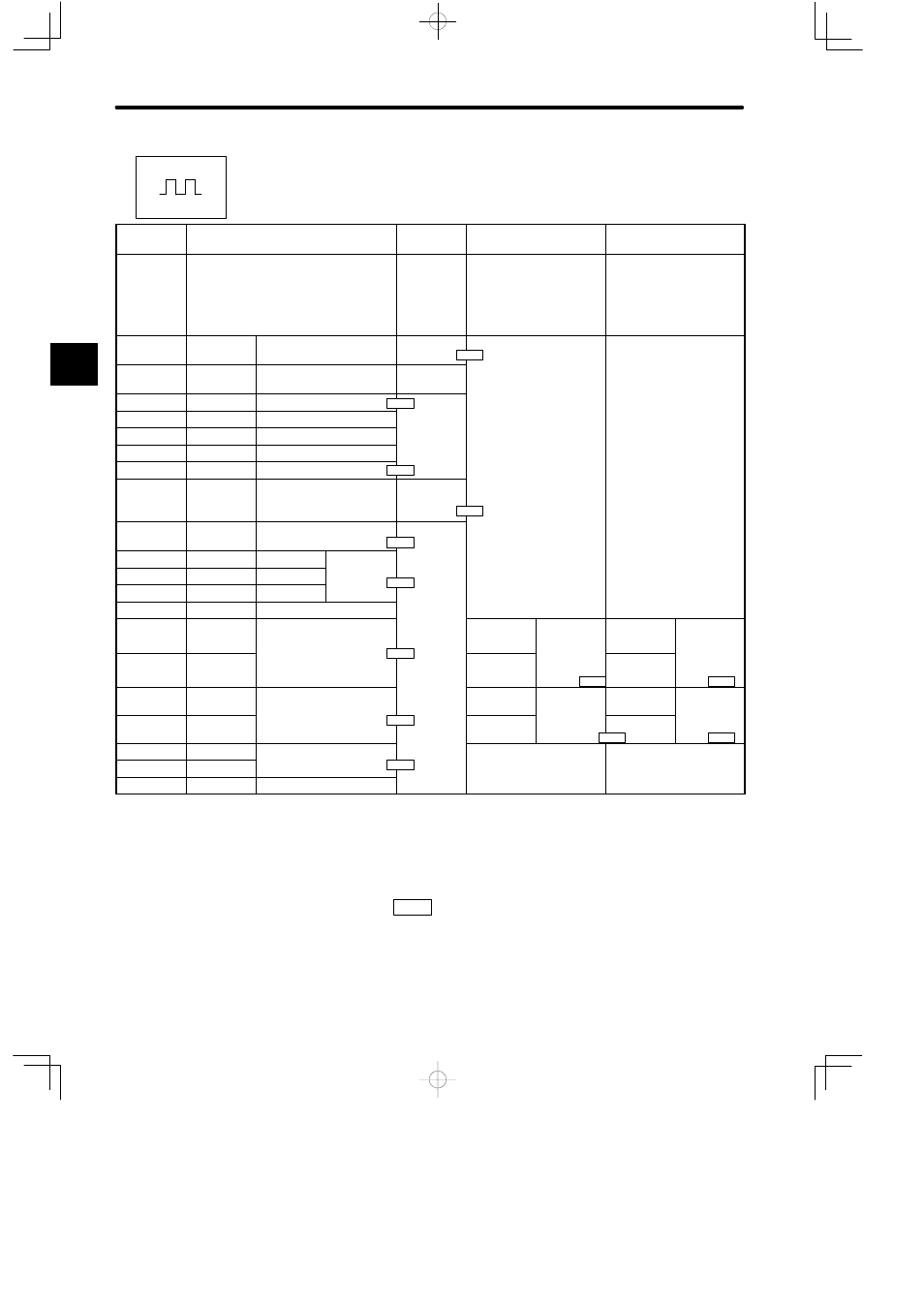
List of I/O Signals for Position Control
Specifica-
tions
Standard Specifications
I/O Signals CCW Pulse + CW Pulse
Reference
90° Different Two-
phase Pulse Reference
CN1 Ter-
minal
Standard Setting
Cn-2A
Cn-2B
Cn-2C
Cn-02 Bits 5, 4, 3 = 0, 0,
1
Cn-02 Bits 5, 4, 3 = 0, 1,
0 (x 1 multiplication)
= 0, 1, 1 (x 2 multiplica-
tion)
= 1, 0, 0 (x 4 multiplica-
tion)
1
IN1
Input signal 1
Input signal
selection
2
IN2
Input signal 2
Input signal
selection
3
SG-COM
Signal ground common
4
---
Unused
5
---
Unused
6
---
Unused
7
ALM
Alarm output
8
OUT2
Output signal 2
Output sig-
nal selec-
tion
9
+24VIN
24-V external power sup-
ply input
10
PCO
Phase C
PG signal
11
PAO
Phase A
g
output
12
PBO
Phase B
13
SG
Signal ground
14
PULS
Reference pulse input
PULS
Forward-
run refer-
ence pulse
PULS
Phase-A
reference
pulse input
15
/PULS
/PULS
ence pulse
input
(CCW)
/PULS
pulse input
16
SIGN
Reference sign input
SIGN
Reverse-
run refer-
SIGN
Phase-B
reference
17
/SIGN
/SIGN
run refer
ence pulse
input (CW)
/SIGN
reference
pulse input
18
CLR
Clear signal input
19
/CLR
g
p
20
FG
Frame ground
Note
1) Information described in the “Standard Specifications” column is also applicable to
blank columns.
2) Number “x.x.x” in box represents a section number corresponding to each signal
name. For example,
2.2.1
represents section 2.2.1.
B
Positions
2.3.4
2.2.4
2.7.1
2.2.4
2.3.4
2.2.3
2.2.2
2.2.2
2.2.2
2.2.2
2.2.2
2.2.2
2.2.2