Yaskawa Sigma Mini User Manual
Page 98
APPLICATIONS
2.6.6 Mode Switch cont.
— 2-54 —
For Speed/
Torque
Control
For Position
Control
Memory
Switch
Cn-01
Memory
Switch Cn-01
Mode Switch Setting
Parameter
Unit
Bit D
Bit C
Bit
D
Bit
C
Bit
B
1
1
-
-
1
Does not use mode
switch.
0
0
0
0
0
Uses torque reference as
a detection point.
(Standard setting)
Cn-0C
Percentage of
rated torque: %
0
1
0
1
0
Uses speed reference as
a detection point.
Cn-0D
Motor speed:
min
−1
1
0
1
0
0
Uses acceleration refer-
ence as a detection point.
Cn-0E
Acceleration
reference in-
side the Servo-
pack:
10 (min
−1
)/s
1
1
0
Uses error pulse as a
detection point.
Cn-0F
Reference unit
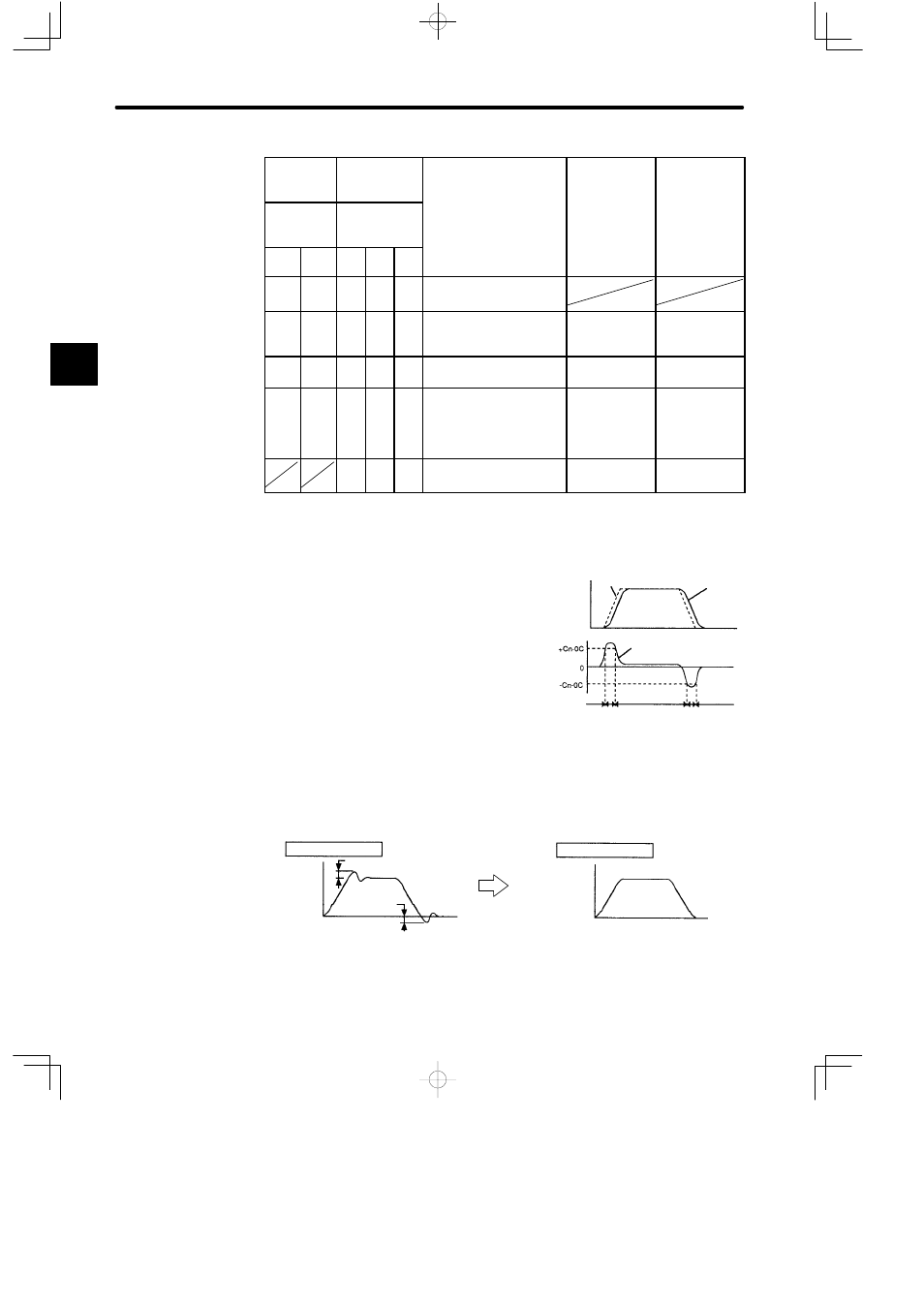
When Torque Reference Is Used as a Detection Point of Mode Switch (Standard
Setting)
If a torque reference exceeds the torque value set
in parameter Cn-0C, the speed loop switches to P
control.
The Servopack is factory set to this standard
mode (Cn-0C = 200).
• Example of Use:
If a mode switch is not used and PI control is always performed, torque may enter a
saturation state during acceleration or deceleration, causing the motor speed to have
overshoot or undershoot.
Using the mode switch suppresses torque saturation and prevents the motor speed
from having overshoot and undershoot.
Without mode switch
Overshoot
Motor
speed
Undershoot
Time
With mode switch
Motor
speed
Time
2
Speed
Reference
speed
Motor
speed
Internal torque
reference
Torque
PI control
P control
PI control
PI control
P control