Servo selection and data sheets, 3 w, 5 w, 10 w – Yaskawa Sigma Mini User Manual
Page 180
SERVO SELECTION AND DATA SHEETS
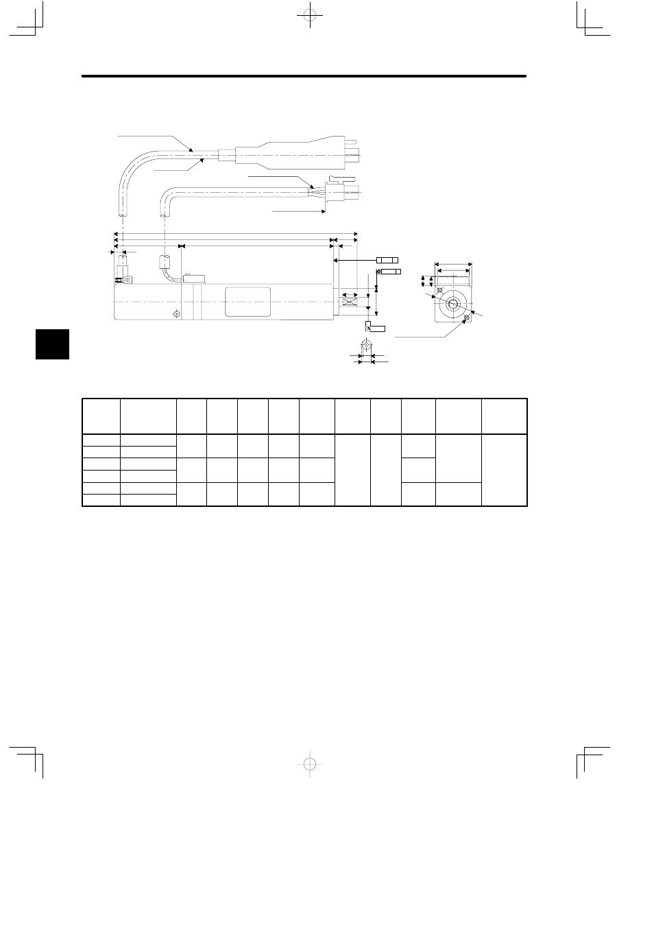
4.4.1 Servomotor Dimensional Drawings
— 4-30 —
• 3 W, 5 W, 10 W
3.3
(0.13)
UL20379
AWG26,UL3266
28 (1.10)
L2
L1
L
10 (0.39)
2.5
(0.098)
6 (0.24)
0.5
(0.02)
3.5 (0.14)
4.3
(0.17)
3.8
(0.15)
12.8 (0.50)
j
15 (0.59)
0.04
0.04 A
A
⊥
A
0.02
φ 16 (0.63)
±0.1 (0.0039)
2 x M2 tap screws 3L
Encoder Leads
Protective Tube
4 mm (0.16) dia.,
black
300 (11.81)
30 (1.18)
Motor Leads
Shaft end
(with flat seat)
(0.0008)
(0.0015)
(0.0015)
(A)
(B)
(A): φ 4
0
−0.008
(φ 0.16
0
−0.0003
)
(B): φ 11
0
−0.018
(φ 0.43
0
−0.0007
)
(A)
Type
SGMM-
Shaft End
Specifica-
tions
L mm
(in)
L1 mm
(in)
L2 mm
(in)
Out-
put W
(HP)
Torque
N
S
m
(lbSm)
Time
Rating
Rated
Speed
(min
−1
)
Approx.
Mass
(g)
Allowable
Radial
Load
N (lb)
Allowable
Thrust
Load
N (lb)
B3CF12 No flat seat
62
(2
)
52
(2 0 )
24
(0 9 )
3
0.00955
(0 002)
Contin-
3000
55
8 (1.8)
4 (0.9)
B3CF13 With flat seat (2.44) (2.05) (0.94)
(0.004)
(0.002)
uous
(
)
(
)
B5CF12 No flat seat
68
(2 68)
58
(2 28)
30
(1 18)
5
0.0159
(0 00 )
60
B5CF13 With flat seat (2.68) (2.28) (1.18)
(0.007)
(0.004)
B9CF12 No flat seat
102
( 02)
92
(3 62)
64
(2 2)
10
0.0318
(0 00 )
100
10 (2.2)
B9CF13 With flat seat (4.02) (3.62) (2.52)
(0.013)
(0.007)
(
)
Note
1) The detector uses a 1024 P/R incremental encoder.
2) The allowable load is applied to the shaft end.
4