Yaskawa Sigma-5 User Manual: Design and Maintenance - Linear Motors User Manual
Page 103
4.2 Settings for Common Basic Functions
4-13
4
Operation
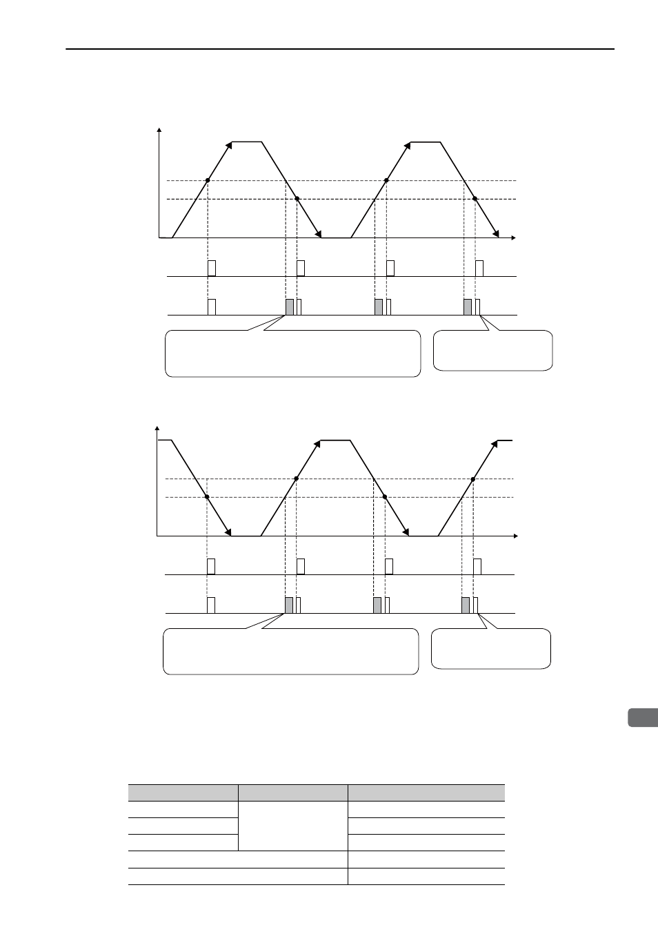
• When Passing 1st Zero Point Signal (Ref) in Forward Direction and Returning after Power ON
• When Passing 1st Zero Point Signal (Ref) in Reverse Direction and Returning after Power ON
(4) Precautions When Using an Incremental Linear Scale by Magnescale
When an incremental linear scale by Magnescale Co., Ltd. is used, the count direction of the linear scale deter-
mines if a phase-C pulse (CN1-21, CN1-22) is output and counted.
Note: The count direction (counting up or down) of the linear scale determines if a phase-C pulse is output. The output of
the pulse does not depend on the setting of the parameter: Pn000.0 (direction selection).
Machine position (Forward direction)
Power ON
Zero point signal
㧔Ref㧕
Phase C
Time
Second pulse is half as wide
as the phase-A pulse.
No zero point signal (Ref) is sent from the linear scale.
However, a phase-C pulse will be sent from the SERVOPACK
when moving in the reverse direction, because it is the same
position from which a phase-C pulse was sent from the
SERVOPACK when moving in a forward direction.
Machine position (Forward direction)
Power ON
Zero point signal
㧔Ref㧕
Phase C
Time
Second pulse is half as wide
as the phase-A pulse.
No zero point signal (Ref) is sent from the linear scale.
However, a phase-C pulse will be sent from the SERVOPACK
when moving in the forward direction, because it is the same
position from which a phase-C pulse was sent from the
SERVOPACK when moving in a reverse direction.
Model
Interpolator
Scale pitch (
μm)
SL710
PL101-RY
MJ620-T13
800
SL720
800
SL730
800
SR75
80
SR85
80