Yaskawa Sigma-5 User Manual: Design and Maintenance - Linear Motors User Manual
Page 59
3.1 Main Circuit Wiring
3-13
3
Wiring and Connection
(3) SERVOPACK Main Circuit Wire
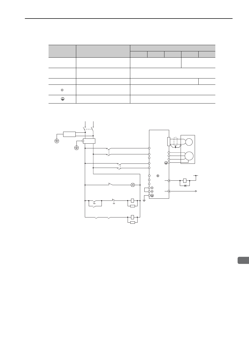
(4) Wiring Example with Single-phase 200 V Power Supply Input
SERVOPACK SGDV-R70A, R90A, 1R6A, 2R8A, and 5R5A with Single-phase 200 V Input
Terminal
Symbols
Name
Model SGDV-A
R70
R90
1R6
2R8
5R5
L1, L2
Main circuit power input
terminals
HIV1.25
HIV2.0
L1C, L2C
Control power supply input
terminals
HIV1.25
U, V, W
Motor connection terminals
HIV1.25
HIV2.0
B1/
, B2
External regenerative resistor
connection terminals
HIV1.25
Ground terminals
HIV2.0 or higher
1KM
1Ry
1PL
1KM
2KM
1SA
1Ry
1KM
2SA
L1
ENC
U
V
W
M
0 V
1Ry
ALM+
ALM
−
3
4
1D
2KM
L3
B2
B3
L2
CN1
1QF
R
T
1FLT
+24 V
1
2
L1C
1KM
L2C
3SA
B1/
1PL
1SA
2SA
3SA
1D:
: Indicator lamp
: Surge absorber
: Surge absorber
: Surge absorber
Flywheel diode
1QF
1FLT
1KM
: Molded-case circuit breaker
: Noise filter
: Magnetic contactor (for control power supply)
2KM: Magnetic contactor (for main power supply)
1Ry: Relay
SERVOPACK
SGDV-
A
(For servo
alarm display)
supply ON
Servo power
supply OFF
Servo power