7 regenerative resistors connections, 1 connecting regenerative resistors, Warning – Yaskawa Sigma-5 User Manual: Design and Maintenance - Linear Motors User Manual
Page 83
3.7 Regenerative Resistors Connections
3-37
3
Wiring and Connection
3.7 Regenerative Resistors Connections
If the ability to absorb regenerative energy is insufficient, connect an external regenerative resistor in the fol-
lowing manner and set the regenerative resistor capacity in Pn600. As for precautions on selecting a regenera-
tive resistor and its specifications, refer to
Σ
-V series Product Catalog (KAEP S800000 42).
3.7.1 Connecting Regenerative Resistors
The following instructions show how to connect the regenerative resistors and SERVOPACKs.
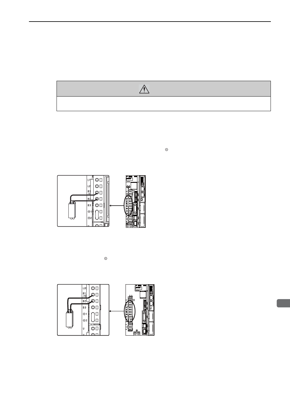
(1) SERVOPACKs: Model SGDV-R70F, R90F, 2R1F, 2R8F, R70A, R90A, 1R6A, 2R8A
Install an external regenerative resistor between the B1/ and B2 terminals. Make the settings for the regener-
ative resistor after it is connected. For information setting the regenerative resistor, refer to 3.7.2 Setting
Regenerative Resistor Capacity.
(2) SERVOPACKs: Model SGDV-3R8A, 5R5A, 7R6A, 120A, 180A, 200A, 330A, 1R9D,
3R5D, 5R4D, 8R4D, 120D, 170D
Disconnect the wiring between the SERVOPACK’s B2 and B3 terminals and connect an external regenerative
resistor between the B1/ and B2 terminals. Make the settings for the regenerative resistor after it is con-
nected. For information setting the regenerative resistor, refer to 3.7.2 Setting Regenerative Resistor Capacity.
Note: Be sure to take out the lead wire between the B2 and B3 terminals.
WARNING
• Be sure to connect the regenerative resistor correctly.
Failure to observe this warning may result in fire or damage to the product.
Enalarged View
Enalarged View