4) connector cn5 for analog monitor, Connection example – Yaskawa Sigma-5 User Manual: Design and Maintenance - Linear Motors User Manual
Page 151
5.1 Adjustments and Basic Adjustment Procedure
5-7
5
Adjustments
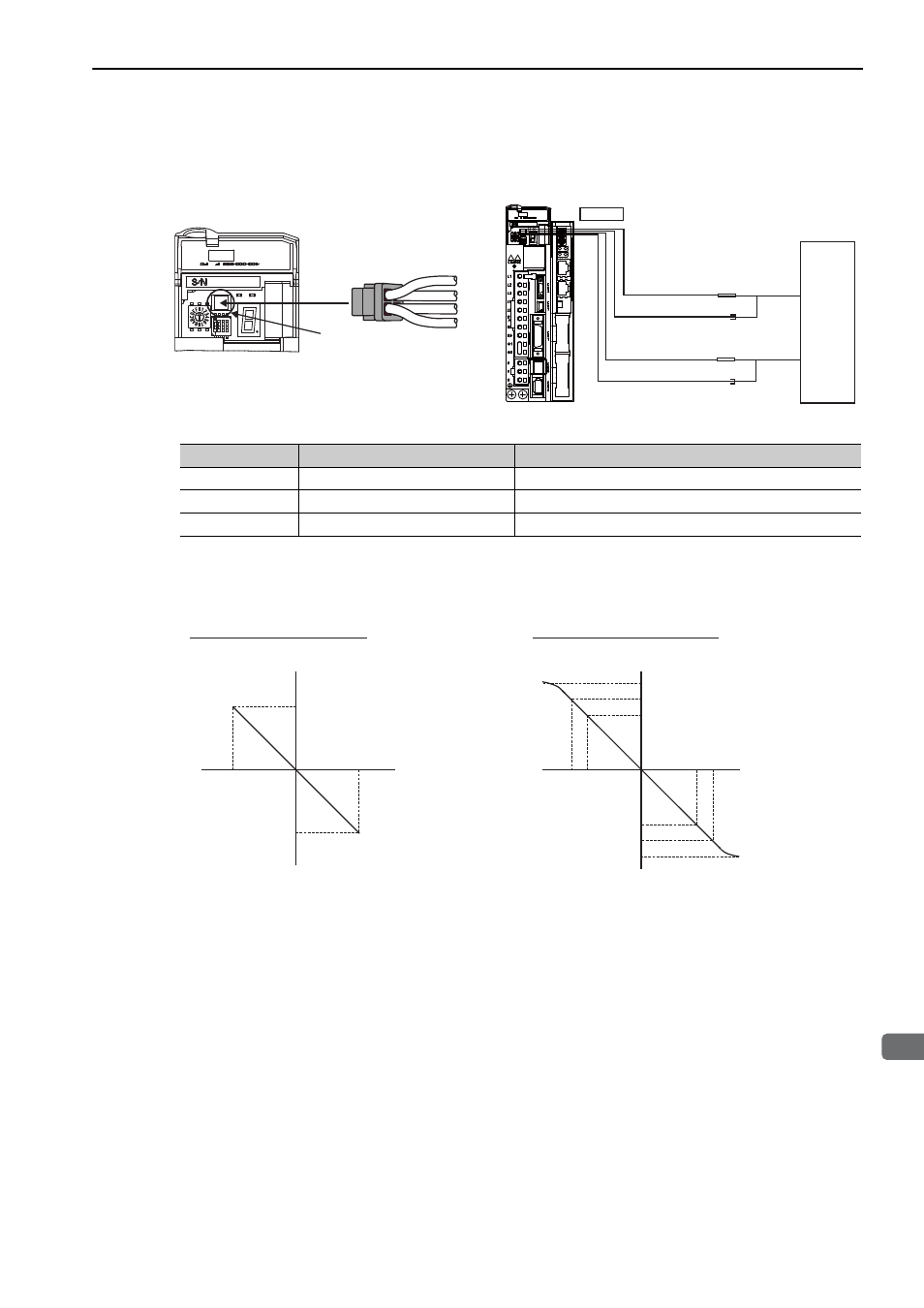
(4) Connector CN5 for Analog Monitor
To monitor analog signals, connect a measuring instrument with cable (JZSP-CA01-E) to the connector CN5.
<Example>
Analog monitor output at n.00 (motor speed setting)
Line Color
Signal Name
Factory Setting
White
Analog monitor 1
Force reference: 1 V/100% rated force
Red
Analog monitor 2
Motor speed: 1 V/1000 mm/s
Black (2 lines)
GND
Analog monitor GND: 0 V
CN5
JZSP-CA01-E
Black
White
Red
Black
CN5
Probe
GND
Probe
GND
Measuring Probe
Measuring Probe
Measuring
Instrument
White
Red
Black
Black
Connection Example
∗Measuring instrument is not included.
+6 V
-6 V
-600
+600
+8 V
-8 V
-800
+800
+10 V approx.
-10 V approx.
+6 V
-6 V
-6000
+6000
Analog monitor
output voltage [V]
Analog monitor
output voltage[V]
When multiplier is set to
×
1:
When multiplier is set to
×
10:
Motor speed
[ ]
Motor speed
[ ]
Note: Linear effective range: within
±
8V
Resolution: 16-bit
mm/s
mm/s