20 (2) brake signal (/bk) setting, 3) brake signal (/bk) allocation, 4) brake on timing after the servomotor stops – Yaskawa Sigma-5 User Manual: Design and Maintenance - Linear Motors User Manual
Page 110
4 Operation
4.2.7 Holding Brakes
4-20
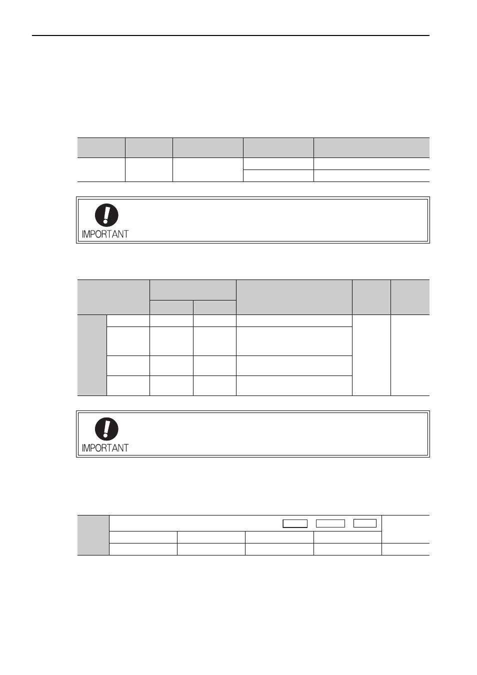
(2) Brake Signal (/BK) Setting
This output signal controls the brake. The allocation of the /BK signal can be changed. Refer to (3) Brake Sig-
nal (/BK) Allocation for allocation.
The /BK signal turns OFF (applies the brake) when an alarm is detected or the SV_OFF command is received.
The brake OFF timing can be adjusted with Pn506.
(3) Brake Signal (/BK) Allocation
Use parameter Pn50F.2 to allocate the /BK signal.
(4) Brake ON Timing after the Servomotor Stops
When the servomotor stops, the /BK signal turns OFF at the same time as the Servo ON command is turned
OFF. Use parameter Pn506 to change the timing to turn OFF the servomotor power after the Servo ON com-
mand has been turned OFF.
Type
Name
Connector
Pin Number
Setting
Meaning
Output
/BK
CN1-1, CN1-2
ON (closed)
Releases the brake.
OFF (open)
Applies the brake.
The /BK signal is still ON during overtravel and the brake is still released.
Parameter
Connector
Pin Number
Meaning
When
Enabled
Classifica-
tion
+ Terminal
- Terminal
Pn50F
n.0
–
–
The /BK signal is not used.
After
restart
Setup
n.1
[Factory
setting]
CN1-1
CN1-2
The /BK signal is output from output
terminal CN1-1, 2.
n.2
CN1-23
CN1-24
The /BK signal is output from output
terminal CN1-23, 24.
n.3
CN1-25
CN1-26
The /BK signal is output from output
terminal CN1-25, 26.
When multiple signals are allocated to the same output terminal, the signals are output
with OR logic. For the /BK signal, do not use the output terminal that is already being
used for another signal.
Pn506
Brake Reference-Servo OFF Delay Time
Classification
Setting Range
Setting Unit
Factory Setting
When Enabled
0 to 50
10 ms
0
Immediately
Setup
Speed
Position
Force