2 parameters – Yaskawa Sigma-5 User Manual: Design and Maintenance - Linear Motors User Manual
Page 288
9.1 List of Parameters
9-3
9
Appendix
9.1.2 Parameters
Parameter
No.
Name
Setting
Range
Units
Factory
Setting
When
Enabled
Classification Reference
Section
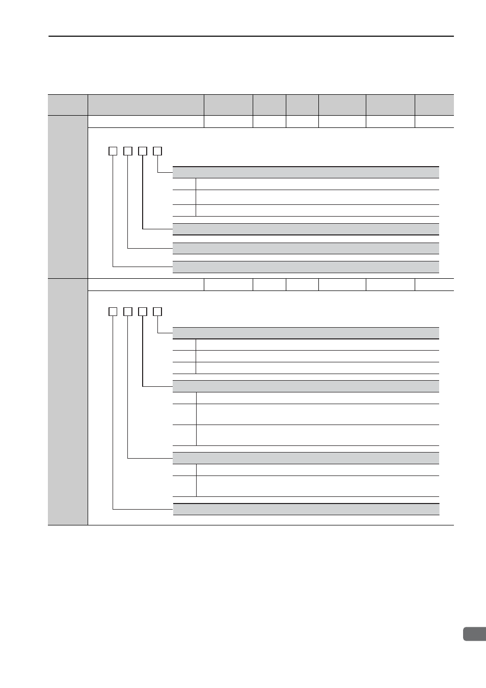
Pn000
Basic Function Select Switch 0
0000 to 00B3
−
0000
After restart
Setup
−
Pn001
Application Function Select Switch 1
0000 to 1122
−
0000
After restart
Setup
−
0
Sets the linear scale counting up (phase-A lead) direction as forward direction.
Direction Selection
4th
digit
3rd
digit
2nd
digit
1st
digit
n.
Reserved (Do not change.)
Reserved (Do not change.)
Reserved (Do not change.)
Sets the linear scale counting down (phase-B lead) direction as forward direction.
(Reverse Movement Mode)
Reserved (Do not change.)
1
2 to 3
(Refer to 4.2.2)
0
1
2
Stops the linear servomotor by applying DB (dynamic brake).
Stops the linear servomotor by applying dynamic brake (DB) and then releases DB.
Makes the linear servomotor coast to a stop state without using the dynamic brake (DB).
0
1
2
Same setting as Pn001.0 (Stops the linear servomotor by applying DB or by coasting).
Sets the force of Pn406 to the maximum value, decelerates the linear servomotor to a stop,
and then sets it to servolock state.
Sets the force of Pn406 to the maximum value, decelerates the linear servomotor to a stop,
and then sets it to coasting state.
Overtravel (OT) Stop Mode
4th
digit
3rd
digit
2nd
digit
1st
digit
n.
0
1
Not applicable to DC power input: Input AC power supply through L1, L2 (, and L3) terminals.
Applicable to DC power input: Input DC power supply between B1/ + and
㧙, or input
DC power supply between B1 and
㧙2.
AC/DC Power Input Selection
Reserved (Do not change.)
Servomotor Power OFF or Alarm Gr.1 Stop Mode
(Refer to 4.2.8)
(Refer to 4.2.3)
(Refer to 3.1.5)