4 absolute linear scale reception sequence, 1) outline of absolute signals, Absolute linear scale transmission sequence – Yaskawa Sigma-5 User Manual: Design and Maintenance - Linear Motors User Manual
Page 129
4.5 Setting Absolute Linear Scale
4-39
4
Operation
4.5.4 Absolute Linear Scale Reception Sequence
The sequence in which the SERVOPACK receives outputs from the absolute linear scale and transmits them to
host controller is shown below.
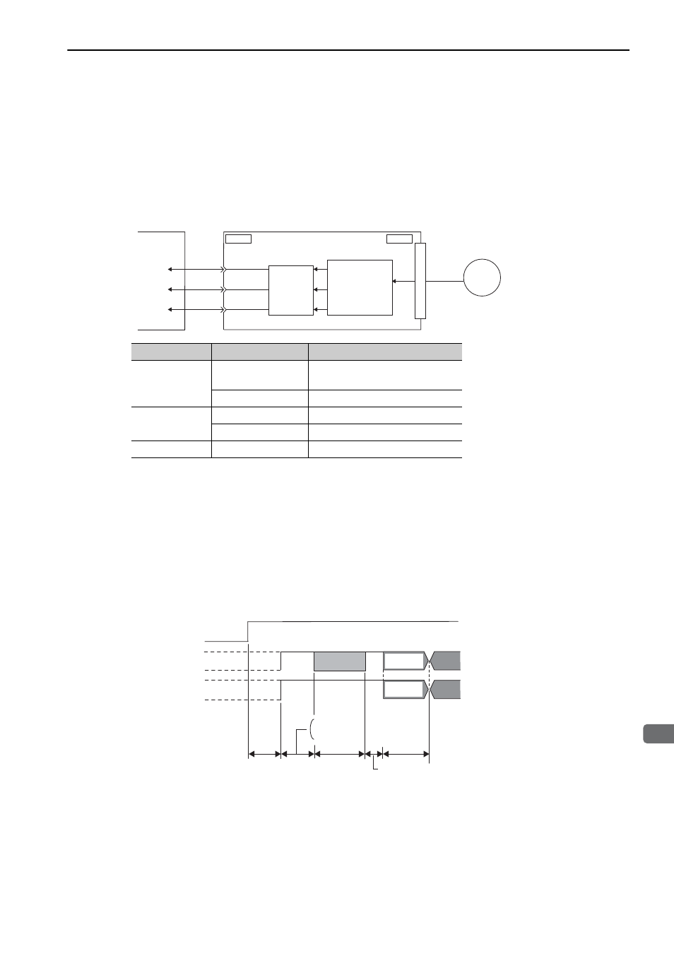
(1) Outline of Absolute Signals
The serial data, pulses, etc., of the absolute linear scale that are output from the SERVOPACK are output from
the PAO, PBO, and PCO signals as shown below.
Note: When host controller receives the data of absolute linear scale, do not perform counter reset using the output of PCO
signal.
(2) Absolute Linear Scale Transmission Sequence and Contents
Absolute Linear Scale Transmission Sequence
1. Send the sensor ON command from the host controller.
2. After 100 ms, set the system to serial data reception-waiting-state. Clear the incremental pulse up/down
counter to zero.
3. Receive eight characters of serial data.
4. The system enters a normal incremental operation state about 400 ms after the last serial data is received.
Serial data:
The current position pulses divided by Pn281 are output in serial data.
One serial data is a value equivalent to 1048576 pulses.
Initial incremental pulses:
The current position pulses divided by Pn281 are output in pulses. The number of output pulses is
between 0 to 1048576, and the output speed is approximately 0.37 µs per pulse.
Signal Name
Status
Contents
PAO
At initialization
Serial data
Initial incremental pulses
Normal time
Incremental pulses
PBO
At initialization
Initial incremental pulses
Normal time
Incremental pulses
PCO
Always
Origin pulses
Serial
data
Linear
scale
ENC
CN1
Converts
serial data to
pulse.
CN2
SERVOPACK
Host controller
Phase A
(PAO, /PAO)
Phase B
(PBO, /PBO)
Phase C
(PCO, /PCO)
Dividing
circuit
(Pn281)
Sensor ON
command
PAO
PBO*
Incremental pulses
Incremental pulses
Undefined
Undefined
(Phase A) (Phase A)
(Phase B) (Phase B)
Serial data
400 ms max.
50 ms
1 to 3 ms
About 15 ms
90 ms typ.
60 ms min.
Initial
incremental
pulses
Initial
incremental
pulses