2 i/o signal connections, 1 i/o signal (cn1) names and functions, 1) input signals – Yaskawa Sigma-5 User Manual: Design and Maintenance - Linear Motors User Manual
Page 64
3 Wiring and Connection
3.2.1 I/O Signal (CN1) Names and Functions
3-18
3.2 I/O Signal Connections
This section describes the names and functions of I/O signals (CN1). Also, connection examples by control
method are shown.
3.2.1 I/O Signal (CN1) Names and Functions
The following table shows the names and functions of I/O signals (CN1).
(1) Input Signals
Note 1. The functions allocated to /SI3, P-OT, N-OT, /SI4, /SI5, and /SI6 input signals can be changed by using the
parameters. Refer to 3.3.1 Input Signal Allocations.
2. If the Forward run prohibited/Reverse run prohibited function is used, the software can be used to stop the SER-
VOPACK. If the application does not satisfy the safety requirements, add an external circuit for safety reasons as
required.
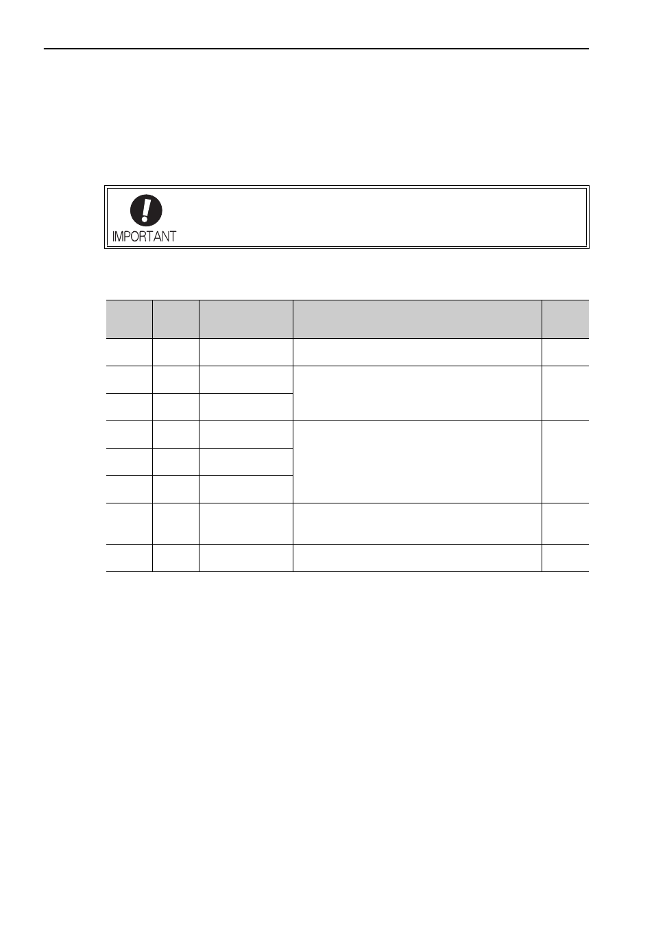
Regarding the allocation and use of I/O signals, they differ in accordance with the con-
nected option module. For details, refer to the manual for the command option module
that is connected.
Signal
Pin No.
Name
Function
Refer-
ence
Section
/SI3
9
Command Option
Module input 3
Connects the external input signal used in the Command
Option Module.
−
P-OT
7
Forward run
prohibited
Overtravel prohibited: Stops linear servomotor when mov-
able part travels beyond the allowable range of motion.
4.2.2
N-OT
8
Reverse run
prohibited
/SI4
10
Command Option
Module input 4
Connects the external input signal used in the Command
Option Module.
−
/SI5
11
Command Option
Module input 5
/SI6
12
Command Option
Module input 6
+24VIN
6
Control power sup-
ply input for
sequence signal
Control power supply input for sequence signals.
Allowable voltage fluctuation range: 11 to 25 V
Note: The
+24-V power supply is not included.
3.4.1
/SI0
13
General-purpose
input
Connects the external input signal used in the Command
Option Module.
−