Arria 10 transceiver native phy signals – Altera Triple Speed Ethernet MegaCore Function User Manual
Page 133
Arria 10 Transceiver Native PHY Signals
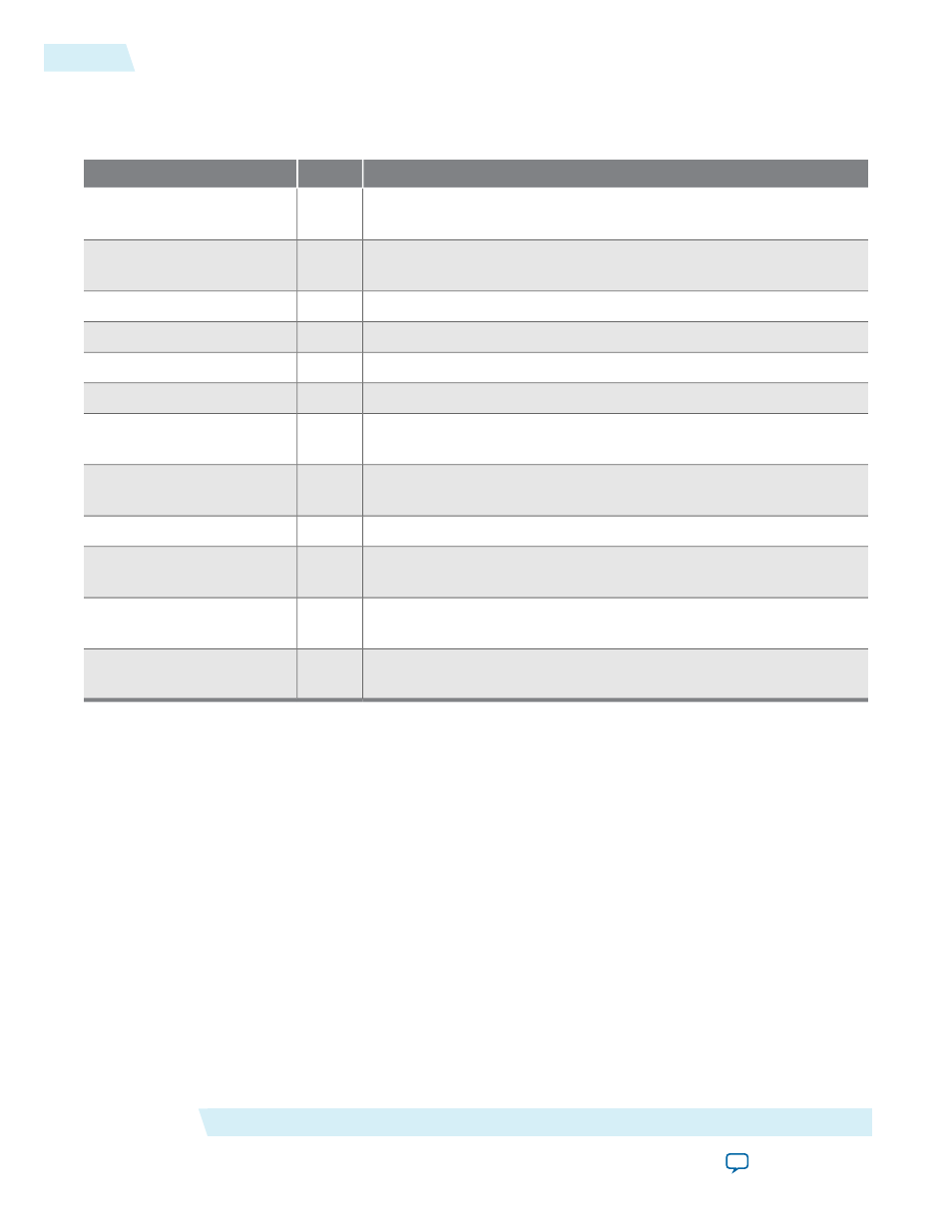
Table 7-22: Arria 10 Transceiver Native PHY Signals
Description
I/O
Name
Serial clock input from the transceiver PLL. The frequency of this clock
depends on the data rate and clock division factor.
I
tx_serial_clk
Reference clock input to the receive clock data recovery (CDR)
circuitry.
I
rx_cdr_refclk
Resets the analog transmit portion of the transceiver PHY.
I
tx_analogreset
Resets the digital transmit portion of the transceiver PHY.
I
tx_digitalreset
Resets the analog receive portion of the transceiver PHY.
I
rx_analogreset
Resets the digital receive portion of the transceiver PHY.
I
rx_digitalreset
When asserted, this signal indicates that the transmit channel is being
calibrated.
O
tx_cal_busy
When asserted, this signal indicates that the receive channel is being
calibrated.
O
rx_cal_busy
Force the receiver CDR to lock to the incoming data.
I
rx_set_locktodata
Force the receiver CDR to lock to the phase and frequency of the input
reference clock.
I
rx_set_locktoref
When asserted, this signal indicates that the CDR PLL is locked to the
incoming data
rx_serial_data
.
O
rx_is_lockedtodata
When asserted, this signal indicates that the CDR PLL is locked to the
incoming reference clock,
rx_cdr_refclk
.
O
rx_is_lockedtoref
Related Information
More information about Gigabit Ethernet (GbE) and GbE with 1588, the connection guidelines for a PHY
design, and how to implement GbE/GbE with 1588 in Arria 10 Transceivers
Interface Signals
Altera Corporation
UG-01008
Arria 10 Transceiver Native PHY Signals
7-18
2014.06.30