Tod synchronizer signals, Tod synchronizer common clock and reset signals, Tod synchronizer interface signals – Altera Triple Speed Ethernet MegaCore Function User Manual
Page 210
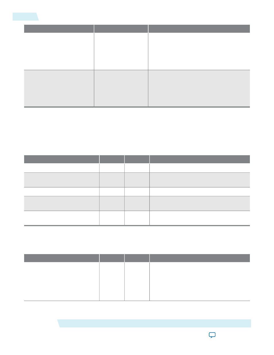
Description
Value
Name
A 4-bit value that defines the reset value for a
nanosecond of period.
The default value is 4'h6 to capture 6.4ns for
156.25 MHz frequency. For 125 MHz frequency
(1G), set this parameter to 4'h8.
Between 0 and 4’hF
PERIOD_NSEC
A 4-bit value that defines the reset value for a
fractional nanosecond of period.
The default value is 16'h6666 to capture 0.4ns
of 6.4ns for 156.25 MHz frequency. For 125
MHz frequency (1G), set this parameter to 16'h0.
Between 0 and 16’hFFFF
PERIOD_FNSEC
ToD Synchronizer Signals
ToD Synchronizer Common Clock and Reset Signals
Table D-3: Clock and Reset Signals for the ToD Synchronizer
Description
Width
Direction
Signal
Clock from master ToD domain.
1
Input
clk_master
Reset signal that is synchronized to the master
ToD clock domain.
1
Input
reset_master
Clock from slave ToD domain.
1
Input
clk_slave
Reset signal that is synchronized to the slave
ToD clock domain.
1
Input
reset_slave
Sampling clock to measure the latency across
the ToD Synchronizer.
1
Input
clk_sampling
ToD Synchronizer Interface Signals
Table D-4: Interface Signals for the ToD Synchronizer
Description
Width
Direction
Signal
Assert this signal to start the ToD synchroniza-
tion process. When this signal is asserted, the
synchronization process continues and the time
of day from the master ToD clock domain will
be repeatedly synchronized with the slave ToD
clock domain.
1
Input
start_tod_sync
ToD Synchronizer
Altera Corporation
UG-01008
ToD Synchronizer Signals
D-4
2014.06.30