Ieee 1588v2 pcs phase measurement clock signal, Ieee 1588v2 phy path delay interface signals – Altera Triple Speed Ethernet MegaCore Function User Manual
Page 148
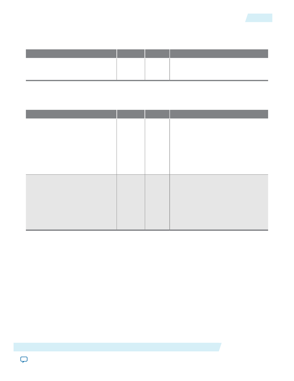
IEEE 1588v2 PCS Phase Measurement Clock Signal
Table 7-34: IEEE 1588v2 PCS Phase Measurement Clock Signal
Description
Width
I/O
Signal
Sampling clock to measure the latency
through the PCS FIFO buffer. The
recommended frequency is 80 MHz.
1
I
pcs_phase_measure_clk
IEEE 1588v2 PHY Path Delay Interface Signals
Table 7-35: IEEE 1588v2 PHY Path Delay Interface Signals
Description
Width
I/O
Signal
Use this bus to carry the path delay on the
transmit datapath. The delay is measured
between the physical network and MII/
GMII to adjust the egress timestamp.
Bits 0 to 9—Fractional number of clock
cycles
Bits 10 to 21—Number of clock cycles
22
I
tx_path_delay_data
Use this bus to carry the path delay on the
receive datapath. The delay is measured
between the physical network and MII/
GMII to adjust the ingress timestamp.
Bits 0 to 9—Fractional number of clock
cycles
Bits 10 to 21—Number of clock cycles
22
I
rx_path_delay_data
Altera Corporation
Interface Signals
7-33
IEEE 1588v2 PCS Phase Measurement Clock Signal
UG-01008
2014.06.30