Altera Triple Speed Ethernet MegaCore Function User Manual
Page 165
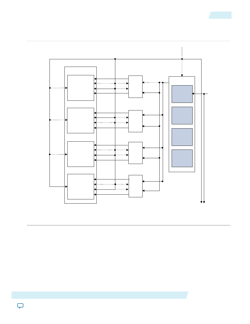
Figure 8-1: Clock Distribution in MAC and SGMII PCS with GXB Configuration—Optimal Case
Figure shows the optimal clock distribution scheme you can achieve in configurations that contain the
10/100/1000 Ethernet MAC, SGMII PCS, and GX transceivers.
tbi _ tx _clk 1
tbi _ rx _ clk 1
tbi _ rx _ clk 2
tbi _ rx _ clk 3
tbi _ rx _ clk 4
Port 4
clk 1
clk 2
clk 3
clk 4
PCS 1
rx _ clk 1
tx _ clk 1
PCS 2
rx _ clk 2
tx _ clk 2
PCS 3
rx _ clk 3
tx _ clk 3
PCS 4
rx _ clk 4
tx _ clk 4
4 -port MAC
Port 2
Port 3
ref _ clk
rx _ clk 1
tx _ clk 1
rx _ clk 2
tx _ clk 2
rx _clk 3
tx _clk 3
rx _ clk 4
tx _ clk 4
ALTGX
(GIGE Mode
)
ALTGX
(GIGE Mode
)
ALTGX
(GIGE Mode
)
Quad
Transceivers
ALTGX
(GIGE Mode
)
c
a
l_
b
lk
_
c
lk
ref _ clk
T
o
s
u
b
s
e
q
u
e
n
t
Q
u
a
d
s
,
if
a
n
y
tbi _ tx _clk 2
tbi _tx _ clk 3
tbi _ tx _ clk 4
Port 1
tx _ clk _ en 1
rx _ clk _ en 1
tx _ clk _ en 2
rx _ clk _ en 2
tx _ clk _ en 3
rx _ clk _ en 3
tx _ clk _ en 1
rx _ clk _ en 1
Note to
:
1. The PMA layer in devices with GX transceivers uses ALTGX megafunctions.
In addition to the aforementioned optimization options, the TBI transmit and receive clocks can be used to
drive the MAC transmit and receive clocks, respectively.
Altera Corporation
Design Considerations
8-3
MAC and PCS With GX Transceivers
UG-01008
2014.06.30