Mii transmit, Mii receive, Ieee 1588v2 timestamp – Altera Triple Speed Ethernet MegaCore Function User Manual
Page 158: Mii transmit -43, Mii receive -43, Ieee 1588v2 timestamp -43, The mii data enable signal, Bus. between frames, Asserted
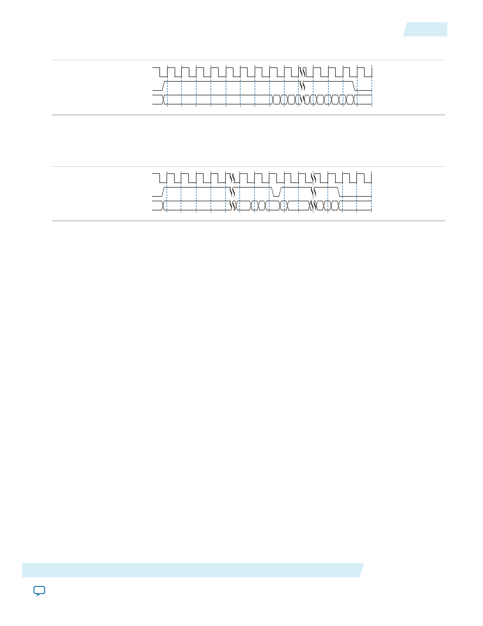
Figure 7-20: RGMII Receive in 1000 Mbps
rx_clk
rx_control
rgmii_in[3:0]
00
5
D
0
5
4
5 E
5
F
5
0
6
0
A frame received on the RGMII interface with a PHY error indication is subsequently transferred on the
Avalon-ST interface with the error signal
rx_err[0]
asserted.
Figure 7-21: RGMII Receive with Error in Gigabit Mode
rx_clk
rx_control
rgmii_in[3:0]
00
5
0
4
6
0
1
0
0
8
0
9
0
The current implementation of the RGMII receive interface expects a positive-delay
rx_clk
relative to the
receive data (the clock comes after the data).
MII Transmit
On transmit, all data transfers are synchronous to the rising edge of
tx_clk
. The MII data enable signal,
m_tx_en,
is asserted to indicate the start of a new frame and remains asserted until the last byte of the frame
is present on
m_tx_d[3:0]
bus. Between frames,
m_tx_en
remains deasserted.
If a frame is received on the FIFO interface with an error (
ff_tx_err
asserted) the frame is subsequently
transmitted with the MII error signal
m_tx_err
for one clock cycle at any time during the frame transfer.
MII Receive
On receive, all signals are sampled on the rising edge of
rx_clk
. The MII data enable signal
m_rx_en
is
asserted by the PHY to indicate the start of a new frame and remains asserted until the last byte of the frame
is present on
m_rx_d[3:0]
bus. Between frames,
m_rx_en
remains deasserted.
If the PHY detects an error on the frame received from the line, the PHY asserts the MII error signal,
m_rx_err
, for at least one clock cycle at any time during the frame transfer.
A frame received on the MII interface with a PHY error indication is subsequently transferred on the FIFO
interface with the error signal
rx_err[0]
asserted.
IEEE 1588v2 Timestamp
The following timing diagrams show the timestamp of frames observed on TX path for the IEEE 1588v2
feature.
Figure below shows the TX timestamp signals for the IEEE 1588v2 feature in a 1-step operation.
In a 1-step operation, a TX egress timestamp is inserted into timestamp field of the PTP frame in the MAC.
You need to drive the 1-step related signal appropriately so that the timestamp can be inserted into the
correct location of the packet. The input signals related to the 2-step operation are not important and can
be driven low or ignored.
Altera Corporation
Interface Signals
7-43
MII Transmit
UG-01008
2014.06.30